Valve Body

DISASSEMBLY
NOTICE:
- Disassembling and reassembling should be conducted on a clean vinyl sheet or mat, or aluminum tray.
- Make the valve slide through the valve hole by Its own weight. Do not forcibly pull out the valve using needle nose pliers. When having difficulty in removing it, slant and shake the valve body or use a magnet hand.
- Do not place the disassembled parts directly on metal work bench or waste cloth.
- Do not use dropped parts.
- Make sure that no burr is identified before assembling.

1. REMOVE DETENT SPRING
Remove the bolt, spring plate and detent spring.

2. REMOVE MANUAL VALVE

3. REMOVE PRESSURE RELEAF VALVE
Remove the bolt, spring seat, spring and ball.

4. REMOVE SOLENOID VALVE
a. Remove the 2 bolts and 3 solenoid valves.
b. Turn the valve body, remove the bolt, lock plate and solenoid valve SLT.
c. Remove the 3 O-rings from the 3 solenoid valves.

5. REMOVE 29 BOLTS

6. REMOVE UPPER VALVE BODY WITH PLATE AS A SINGLE UNIT
Hold the valve body plate to the upper valve body, and remove the upper valve body with the plate.
NOTICE: Be careful that the check balls and strainer do not fall out.

7. REMOVE OIL STRAINER
Remove the 3 oil strainers from the plate.

8. REMOVE CHECK VALVE AND SPRING
9. REMOVE 10 CHECK BALLS
10. REMOVE 2 GASKETS FROM PLATE
REASSEMBLY

1. POSITION NEW No.1 GASKET ON UPPER VALVE BODY
Align a new No.1 gasket with each bolt hole.
2. POSITION VALVE BODY PLATE ON No.1 GASKET
Align the plate with each bolt hole.

3. POSITION NEW No.2 GASKET ON PLATE
Align a new No.2 gasket with each bolt hole.
4. INSTALL 10 CHECK BALLS

5. INSTALL SPRING AND CHECK VALVE

6. INSTALL OIL STRAINER
Install the 3 oil strainers to the plate.

7. PLACE UPPER VALVE BODY WITH PLATE AND GASKETS ON TOP OF LOWER VALVE BODY
Align each bolt hole with the gasket in the valve body.
NOTICE: Be careful that the check ball and strainer do not fall out.

8. INSTALL 29 BOLTS TO UPPER VALVE BODY
Torque: 6.4 Nm (65 kgf-cm, 47 ft. lbs.)
HINT: Each bolt length is indicated.
Bolt length:
Bolt A: 20 mm (0.79 inch)
Bolt B: 28 mm (1.10 inch)
Bolt C: 40 mm (1.57 inch)
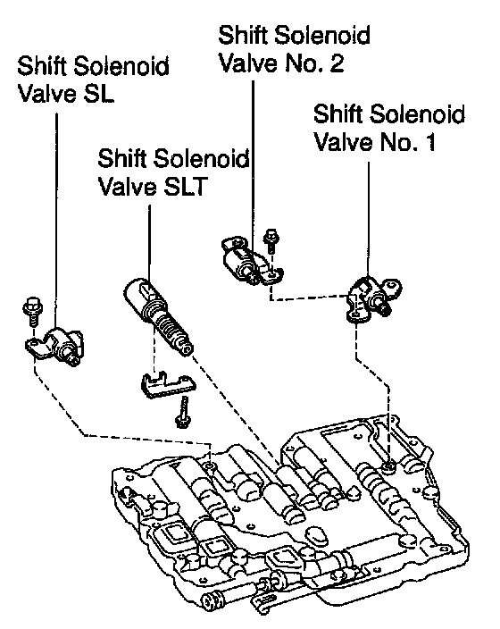
9. INSTALL SOLENOID VALVE
a. Install 3 new O-rings to the 3 solenoid valves.
b. Install the solenoid valve and lock plate with bolt.
Torque: 10 Nm (100 kgf-cm, 7 ft. lbs.)
c. Install the 3 solenoid valves with the 3 bolts.
Torque: 10 Nm (100 kgf-cm, 7 ft. lbs.)
10. INSTALL MANUAL VALVE

11. INSTALL PRESSURE RELEAF VALVE
Install the spring, ball, spring seat and bolt.
Torque: 6.9 Nm (70 kgf-cm, 61 inch lbs.)

12. INSTALL DETENT SPRING
Install the detent spring and spring plate with the bolt.
Torque: 10 Nm (100 kgf-cm, 7 ft. lbs.)
13. MAKE SURE MANUAL VALVE MOVES SMOOTHLY