Part 1
REASSEMBLY
NOTICE:
- The automatic transmission is composed of highly precision-finished parts, necessitating careful inspection before reassembly because even a small nick could cause fluid leakage or affect the performance. The instructions here are organized so that you work on only one component group at a time. This will help avoid confusion from similar-looking parts of different sub-assemblies being on your workbench at the same time. The component groups are inspected and repaired from the converter housing side. As much as possible, complete the inspection, repair and reassembly before proceeding to the next component group. If a defect Is found in a certain component group during reassembly, inspect and repair this group immediately. If a component group cannot be assembled because parts are being ordered, be sure to keep all parts of the group in a separate container while proceeding with disassembly, inspection, repair and reassembly of other component groups.
Recommended ATF: D-II or DEXRON(R)III (DEXRON(R)II)
- All disassembled parts should be washed clean and any fluid passages and holes should be blown through with compressed air.
- Dry all parts with compressed air-never use shop rags.
- When using compressed air, always aim away from yourself to prevent accidentally spraying ATF or kerosene on your face.
- The recommended ATF or kerosene should be used for cleaning.
- After cleaning, the parts should be arranged in the correct order for efficient inspection, repairs, and reassembly.
- When disassembling a valve body, be sure to match each valve together with the corresponding spring.
- New discs for the brakes and clutches that are to be used for replacement must be soaked in ATF for at least 15 minutes before reassembly.
- All oil seal rings, clutch discs, clutch plates, rotating parts, and sliding surfaces should be coated with ATF prior to reassembly.
- All gaskets and rubber O-rings should be replaced.
- Do not apply adhesive cements to gaskets and similar parts.
- Make sure that the ends of a snap ring are not aligned with one of the cutouts and are installed in the groove correctly.
- If a worn bushing is to be replaced, the sub-assembly containing the bushing must also be replaced.
- Check thrust bearings and races for wear or damage. Replace if necessary. Use petroleum jelly to keep parts in place.
- When working with FIPG material, you must observe the following.
Using a razor blade and a gasket scraper, remove all the old packing Formed In Place Gasket (FIPG) material from the gasket surface.
Thoroughly clean all components to remove all the loose material. Clean both sealing surfaces with a non-residue solvent.
Parts must be reassembled within 10 minutes of application. Otherwise, the packing Formed In Place Gasket (FIPG) material must be removed and reapplied.

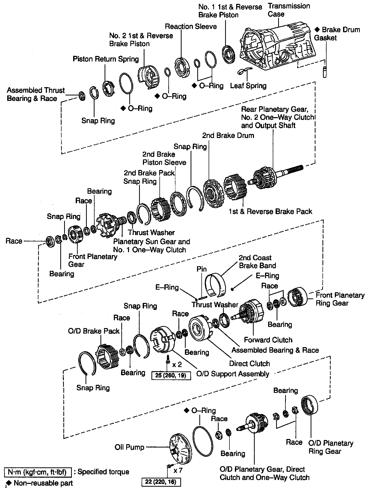
BEARING AND RACES INSTALLATION POSITION AND DIRECTION
1. INSTALL COMPONENTS OF 1ST & REVERSE BRAKE PISTON
a. Coat 3 new O-rings with ATF.

b. Install the 2 O-rings on the No.1 1st & reverse brake piston.
c. Install the O-ring on the reaction sleeve.
d. Install the No.1 1st & reverse brake piston to the reaction sleeve.

e. Coat a new O-ring with ATF and install it on the No.2 1st & reverse brake piston.
f. Install the No.1 1st & reverse brake piston with the reaction sleeve onto the No.2 1st & reverse brake piston.

g. Align the teeth of the No.2 1st & reverse brake 1st & reverse brake piston into the proper grooves.
h. Being careful not to damage the O-rings, press in the No.2 and No.1 1st & reverse brake pistons into the transmission case.

i. Place the piston return spring onto the No.2 1st & reverse brake piston.

j. Set SST as shown, and compress the return spring with SST
NOTICE: Stop compressing when the spring sheet is lowered to the place 1 - 2 mm (0.039 - 0.078 inch) from the snap ring groove, preventing the spring sheet from being deformed.
SST 09350-30020 (09350-07050)
k. Using a screwdriver, install the snap ring. Make sure the end gap of the snap ring is not aligned with the spring retainer claw.

2. CHECK PISTON STROKE OF 1ST & REVERSE BRAKE
Make sure the 1st & reverse brake pistons move smoothly when applying and releasing the compressed air into the transmission case.

3. INSTALL LEAF SPRING
4. INSTALL REAR PLANETARY GEAR UNIT WITH 2ND BRAKE DRUM, 1ST & REVERSE BRAKE PACK AND OUTPUT SHAFT

a. Install the flange with the rounded edge facing forward.
b. Reinstall the plates and discs.
Install in order: P = Plate D = Disc
5VZ-FE:
D - P - P - P - P - P - P - P - D - P - D - P
2UZ-FE:
D - P - D - P - D - P - D - P - D - P - D - P - D - P

c. Install the 2nd brake drum assembly.

d. Coat the assembled bearing & race with petroleum jelly and install it onto the case.

Assembled bearing & race diameter

e. Align the teeth of the 2nd brake drum, flange, discs and plates.

f. Align the splines of the transmission case and assembled rear planetary gear, 2nd brake drum, 1st & reverse brake pack and output shaft, indicated by A.
g. Install the assembled output shaft.

h. Hold the output shaft with wooden blocks or equivalents.

i. Using SST, install the snap ring.
SST 09350-30020 (09350-07060)

5. CHECK PACK CLEARANCE OF 1ST & REVERSE BRAKE
Using a feeler gauge, measure the clearance between the plate and 2nd brake drum.
Clearance: 0.50 - 1.02 mm (0.0197 - 0.0402 inch)
If the values are non-standard, select another flange.
HINT: There are 6 different thicknesses for the flange.

Flange thickness

6. INSTALL 2ND BRAKE PISTON SLEEVE

7. INSTALL NEW BRAKE DRUM GASKET
a. Coat a new gasket with ATF
b. Install the brake drum gasket.
8. INSTALL No.1 ONE-WAY CLUTCH

a. Install the No.1 thrust washer onto the 2nd brake.

b. Install the No.1 one-way clutch.
9. INSTALL FLANGE, PLATE AND DISC OF 2ND BRAKE

a. Install the plate with the rounded edge side of the plate facing the discs.
Plate thickness: 2.5 mm (0.098 inch)
b. Install the plates and discs.
Install In order: P = Plate D = Disc
D - P - D - P - D - P - D - P - D - P

c. Using a screwdriver, install the snap ring.

10. CHECK PACK CLEARANCE OF 2ND BRAKE
Using a feeler gauge, measure the clearance between the snap ring and flange.
Clearance: 0.50 - 1.76 mm (0.0197 - 0.0693 inch)
If the values are non-standard, check for an improper installation.

11. INSTALL PLANETARY SUN GEAR
While turning the planetary sun gear clockwise, install it into the No.1 one-way clutch.
HINT: Confirm the thrust washer is installed correctly.
12. INSTALL FRONT PLANETARY GEAR

a. Coat the bearing and race with petroleum jelly and install them onto the front planetary gear.

Bearing and race diameter

b. Install the front planetary gear to the sun gear input drum.

c. Using SST, install the snap ring.
SST 09350-30020 (09350-07070)
d. Remove the wooden blocks or equivalent under the output shaft.

e. Coat the race with petroleum jelly and install it onto the front planetary gear.

Race diameter
13. INSTALL 2ND COAST BRAKE BAND

a. Install the 2nd coast brake band to the case.

b. Install the pin through the brake band.

c. Using needle-nose pliers, install the E-ring to the pin.
14. INSTALL DIRECT CLUTCH TO FORWARD CLUTCH

a. Install the assembled bearing & race and thrust washer to the forward clutch.

b. Install the direct clutch to the forward clutch.
15. INSTALL FRONT PLANETARY RING GEAR TO FORWARD AND DIRECT CLUTCH

a. Coat the bearing and race with petroleum jelly and install them onto the forward clutch.

Bearing and race diameter

b. Coat the race with petroleum jelly and install it onto the front planetary ring gear.

Race diameter

c. Align the flukes of the discs in the forward clutch.

d. Align the splines of the front planetary ring gear with the flukes of the discs and install the front planetary ring gear to the forward clutch.
16. INSTALL ASSEMBLED DIRECT CLUTCH, FORWARD CLUTCH AND FRONT PLANETARY RING GEAR INTO CASE

a. Coat the bearing and race with petroleum jelly and install them onto the ring gear.

Bearing and race diameter

b. Install the assembled direct clutch, forward clutch and front planetary ring gear into the transmission case.

c. Using vernier calipers, measure the distance between the sun gear input drum and direct clutch drum.
Height: 5.3 - 7.3 mm (0.209 - 0.287 inch)
If the value is non-standard, check for an improper installation.

d. Coat the assembled bearing & race with petroleum jelly and install it onto the forward clutch.

Assembled bearing & race diameter
17. INSTALL 2ND COAST BRAKE COVER, PISTON ASSEMBLY AND SPRING

a. Coat 2 new O-rings with ATF and install them to the cover.
b. Install the spring, piston assembly and cover to the case.

c. Using SST, install the snap ring.
SST 09350-30020 (09350-07060)
18. CHECK PISTON ROD STROKE OF 2ND COAST BRAKE

a. Place a mark on the 2nd coast brake piston rod.

b. Using SST, measure the stroke while applying and releasing compressed air (392 kPa, 4.0 kgf/cm2, 57 psi).
SST 09240-00020
Piston rod stroke: 1.5 - 3.0 mm (0.059 - 0.118 inch)
If the stroke is more than the specified, replace the piston rod.
Piston rod length:
71.4 mm (2.811 inch)
72.9 mm (2.870 inch)
If it is still more than standard value, replace the brake band with a new one.
19. INSTALL O/D SUPPORT ASSEMBLY

a. Coat the race with petroleum jelly and install it onto the O/D support assembly.

Bearing diameter

b. Confirm the thrust washer is installed correctly.
HINT: Make sure that the lug shape matches the hole on the O/D support assembly.

c. Using 2 bolts of SST, aim the bolt and oil holes of the O/D support toward the valve body side, and align them with the bolt holes of the transmission case and insert.
SST 09350-30020 (09350-07020)
d. Temporarily tighten the 2 bolts.

e. Using SST, install the snap ring.
SST 09350-30020 (09350-07060)
HINT: Face the snap ring open end toward the valve body.

f. Torque the 2 bolts.
Torque: 25 Nm (260 kgf-cm, 19 ft. lbs.)

20. CHECK OUTPUT SHAFT
a. Using a dial indicator, measure the end play of the output shaft by hand.
End play: 0.27 - 0.86 mm (0.0106 - 0.0339 inch)
If the value is non-standard, check for an improper installation.
b. Check to see that output shaft rotates smoothly.
21. INSTALL O/D BRAKE PACK

a. Install the 4.0 mm (0.157 inch) thick flange (flat ring) with the rounded edge side of the flange facing the discs.
b. Install the plates and discs.
Install in order: P = Plate D = Disc
5VZ-FE: D - P - D - P - D - P - D
2UZ-FE: D - P - D - P - D - P - D - P - D
c. Install the flange (stepped ring) with the flat side of the flange facing the disc.

d. Using a screwdriver, install the snap ring.
22. CHECK PISTON STROKE OF O/D BRAKE

a. Place SST and a dial indicator onto the O/D brake piston.
SST 09350-30020 (09350-06120)

b. Measure the stroke while applying and releasing compressed air (392 kPa, 4.0 kgf/cm2, 57 psi).
Piston stroke: 1.32 - 1.62 mm (0.0520 - 0.0638 inch)
If the piston stroke is less than the limit, parts may have been assembled incorrectly, check and reassemble again.
If the piston stroke is non-standard, select another flange.
HINT: There are 7 different thicknesses for the flange.

Flange thickness