Part 2


DISASSEMBLY

25. 5VZ-FE:
REMOVE THROTTLE CABLE
a. Remove the retaining bolt and pull out the throttle cable.
b. Remove the O-ring from the cable.

26. 2UZ-FE:
REMOVE TRANSMISSION PLUG
a. Remove the bolt and pull out the plug.
b. Remove the O-ring.
27. REMOVE PARKING LOCK ROD AND PAWL

a. Remove the 3 bolts and parking lock pawl bracket.

b. Disconnect the parking lock rod from the manual valve lever.

c. Remove the E-ring from the shaft.
d. Pull the parking lock pawl shaft out from the front side, then remove the pawl and spring.
28. REMOVE MANUAL VALVE LEVER SHAFT

a. Using a hammer and screwdriver, cut off the spacer and remove it from the shaft.

b. Using a pin punch, drive out the pin.
HINT: Slowly drive out the pin so it does not fall into the transmission case.
c. Pull out the manual valve lever shaft through the case and remove the manual valve lever.

d. Using a screwdriver, remove the 2 oil seals.
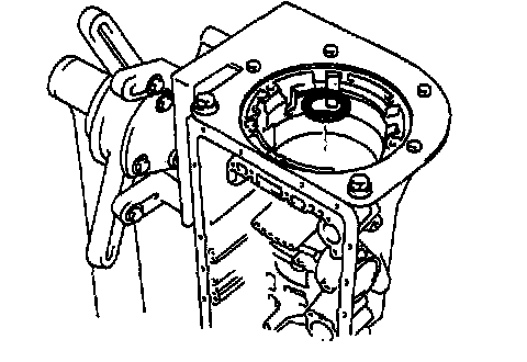
29. REMOVE OIL PUMP
a. Stand up the transmission.

b. Remove the 7 bolts holding the oil pump to the transmission case.

c. Using SST, remove the oil pump.
SST 09610-20012

d. Remove the race from the oil pump.
e. Remove the O-ring from the oil pump.
30. REMOVE O/D PLANETARY GEAR, O/D DIRECT CLUTCH AND ONE-WAY CLUTCH

a. Remove the O/D planetary gear, O/D direct clutch and one-way clutch from the transmission case.

b. Remove the race and assembled bearing & race.

c. Remove the O/D planetary ring gear from the transmission case.

d. Remove the bearing and 2 races from the O/D planetary ring gear.
31. CHECK PISTON STROKE OF O/D BRAKE

a. Place SST and a dial indicator onto the O/D brake piston.
SST 09350-30020 (09350-06120)

b. Measure the stroke while applying and releasing compressed air (392 kPa, 4.0 kgf/cm2, 57 psi).
Piston stroke: 1.32 - 1.62 mm (0.0520 - 0.0638 inch)
If the values are non standard, inspect the disc.
32. REMOVE O/D BRAKE PACK

a. Using a screwdriver, remove the snap ring.

b. Remove the O/D brake pack.
33. CHECK PISTON ROD STROKE OF 2ND COAST BRAKE

a. Place a mark on the 2nd coast brake piston rod.

b. Using SST, measure the stroke while applying compressed air (392 kPa, 4.0 kgf/cm2, 57 psi).
SST 09350-30020 (09350-00020)
Piston stroke: 1.5 - 3.0 mm (0.059 - 0.118 inch)
If the value is non-standard, inspect the brake band.
34. REMOVE 2ND COAST BRAKE COVER, PISTON ASSEMBLY AND SPRING

a. Using SST, remove the snap ring.
SST 09350-30020 (09350-07060)

b. Applying compressed air (392 kPa, 4.0 kgf/cm2, 57 psi) to the oil hole, remove the 2nd coast brake cover, piston assembly and spring.
c. Remove the 2 O-rings from the cover.
35. REMOVE O/D SUPPORT ASSEMBLY

a. Remove the 2 bolts holding the O/D support assembly to the case.

b. Using SST, remove the snap ring.
SST 09350-30020 (09350-07060)

c. Using SST, remove the O/D support assembly.
SST 09350-30020 (09350-07020)

d. Remove the assembled bearing & race and race from the O/D support.
36. REMOVE DIRECT CLUTCH AND FORWARD CLUTCH

a. Remove the direct clutch with the forward clutch from the case.
b. Remove the bearing from the direct clutch.

c. Remove the direct clutch form the forward clutch.

d. Remove the assembled bearing & race, thrust washer and race from the forward clutch.
37. REMOVE 2ND COAST BRAKE BAND

a. Using a screwdriver, remove the E-ring from the pin.
HINT: Apply the grease to the E-ring and pin before the work so that the ring does not fly out.
b. Remove the pin from the brake band.
c. Remove the E-ring from the pin.

d. Remove the 2nd coast brake band from the case.
38. REMOVE FRONT PLANETARY RING GEAR

a. Remove the front planetary ring gear from the case.

b. Remove the assembled bearing & race bearing and race from the front planetary ring gear.

c. Remove the race from the front planetary gear.

d. With wooden blocks or equivalent under the output shaft, stand the transmission on the output shaft.

e. Using SST, remove the snap ring.
SST 09350-30020 (09350-07070)
HINT: Pushing the output shaft towards the front makes it easier to remove.

f. Remove the front planetary gear from the case.

g. Using a screwdriver, remove the bearing and race from the front planetary gear.

39. REMOVE PLANETARY SUN GEAR AND No.1 ONE WAY CLUTCH
a. Remove the planetary sun gear and No.1 one-way clutch from the case.
b. Remove the thrust washer.

40. CHECK PACK CLEARANCE OF 2ND BRAKE
Using a feeler gauge, measure the clearance between the snap ring and flange.
Clearance: 0.50 - 1.76 mm (0.0197 - 0.0693 inch)
If the values are non-standard, inspect the disc.
41. REMOVE 2ND BRAKE PACK

a. Using a screwdriver, remove the snap ring.

b. Remove the 2nd brake pack.

42. CHECK PACK CLEARANCE OF 1ST & REVERSE BRAKE
Using a feeler gauge, measure the clearance between the plate and 2nd brake drum.
Clearance: 0.50 - 1.02 mm (0.0197 - 0.0402 inch)
If the values are non-standard, inspect the discs.

43. REMOVE 2ND BRAKE PISTON SLEEVE
Using a screwdriver, remove the 2nd brake piston sleeve.
44. REMOVE 2ND BRAKE DRUM, 1ST & REVERSE BRAKE, REAR PLANETARY GEAR, No.2 ONE-WAY CLUTCH AND OUTPUT SHAFT

a. Using SST and 2 screwdrivers, remove the snap ring.
SST 09350-30020 (09350-07060)

b. Remove the 2nd brake drum, 1st & reverse brake pack and rear planetary gear, No.2 one-way clutch and output shaft.
c. Remove the assembled thrust bearing & race from the case.

d. Remove the 2nd brake drum.

e. Remove the 1st & reverse brake pack.

45. REMOVE LEAF SPRING

46. REMOVE BRAKE DRUM GASKET

47. CHECK PISTON STROKE OF 1ST & REVERSE BRAKE
Make sure the 1st & reverse brake pistons move smoothly when applying and releasing the compressed air into the transmission case.
48. REMOVE No.2 1ST & REVERSE BRAKE PISTON

a. Set SST on the spring retainer, and compress the return spring.
SST 09350-30020 (09350-07050)
NOTICE: Stop compressing when the spring sheet is lowered to the place 1 - 2 mm (0.039 - 0.078 inch) from the snap ring groove, preventing the spring sheet from being deformed.
b. Using snap ring pliers, remove the snap ring.
c. Remove the piston return spring.
d. Hold the No.2 1st & reverse brake piston with hand, apply compressed air (392 kPa, 4.0 kgf/cm2, 57 psi) to the transmission case to remove the No.2 1st & reverse brake piston.

e. Remove the No.2 1st & reverse brake piston.
If the piston does not pop out with compressed air, lift the position out with needle-nose pliers.
f. Remove the O-ring from the No.2 1st & reverse brake piston.

g. Install SST behind the reaction sleeve and gradually lift it out of the transmission case.
SST 09350-30020 (09350-07080)
h. Remove the O-ring from the reaction sleeve.

i. Install SST behind the No.1 1st & reverse brake piston and gradually lift it out of the transmission case.
SST 09350-30020 (09350-07090)
j. Remove the 2 O-rings from the No.1 1st & reverse brake piston.