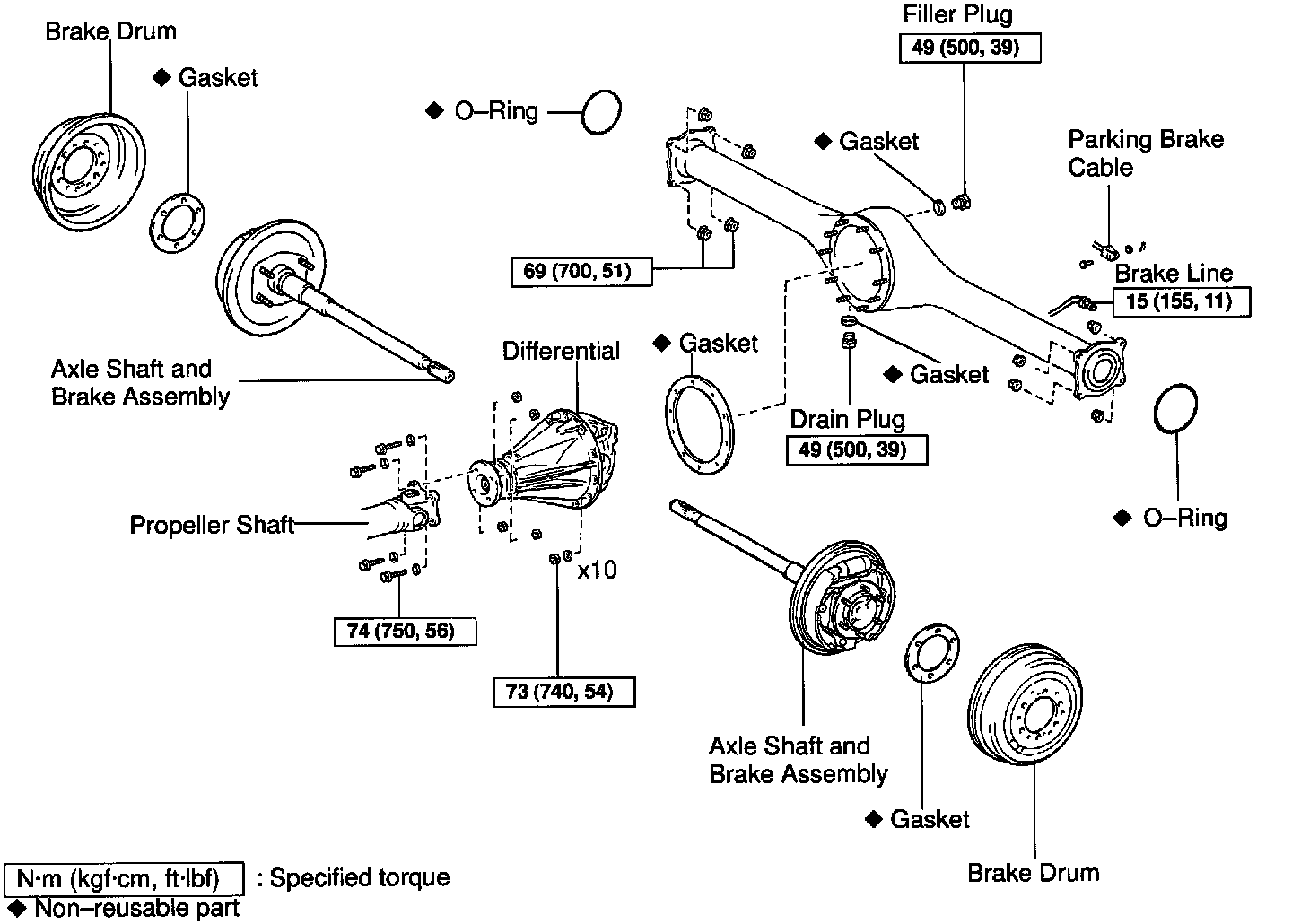
Rear Differential
Part 1 Of 2:
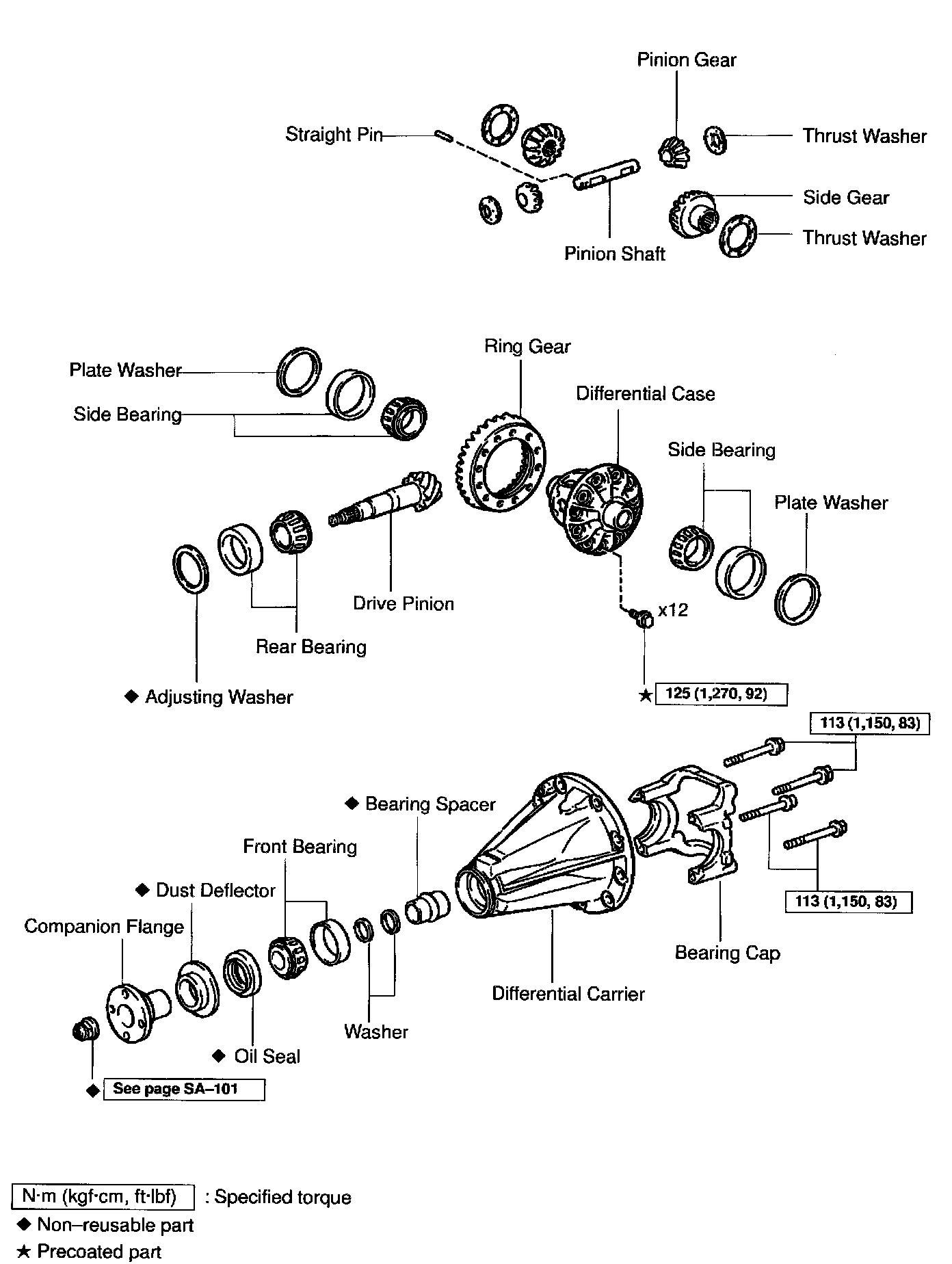
Part 2 Of 2:
DISASSEMBLY

1. CHECK COMPANION FLANGE RUNOUT
Using a dial indicator, measure the vertical and lateral runout of the companion flange.
Maximum runout: 0.09 mm (0.0035 inch)
If the runout exceeds the maximum, replace the companion flange.

2. CHECK RING GEAR RUNOUT
Using a dial indicator, measure the ring gear runout.
Maximum runout: 0.05 mm (0.0020 inch)
If the runout exceeds the maximum, replace the ring gear.

3. CHECK RING GEAR BACKLASH
Using a dial indicator, while holding the companion flange, measure the ring gear backlash.
Backlash: 0.13-0.18 mm (0.0051-0.0071 inch)
HINT: Measure at 3 or more positions around the circumference of the ring gear. If the backlash is not within the specified value, adjust the side bearing preload or repair as necessary.
4. CHECK TOOTH CONTACT BETWEEN RING GEAR AND DRIVE PINION

5. CHECK SIDE GEAR BACKLASH
Using a dial indicator, measure the side gear backlash while holding one pinion gear toward the case.
Backlash: 0.05-0.20 mm (0.0020-0.0079 inch)
If the backlash is not within the specified value, replace the side gear thrust washer of the different thickness.

6. MEASURE DRIVE PINION PRELOAD
Using a torque wrench, measure the preload of the drive pinion using the backlash between the drive pinion and ring gear.
Preload (at starting): 0.5-0.8 Nm (5-8 kgf-cm, 4.3-6.9 inch lbs.)
7. CHECK TOTAL PRELOAD
Using a torque wrench, measure the total preload with the teeth of the drive pinion and ring gear in contact.
Total preload (at starting):
Drive pinion preload plus 0.4-0.6 Nm (4-6 kgf-cm, 3.5-5.2 inch lbs.)
If necessary, disassemble and inspect the differential.
8. REMOVE COMPANION FLANGE
a. Using a chisel and hammer, unstake the staked part of the nut.

b. Using SST to hold the flange, remove the nut.
SST 09330-00021
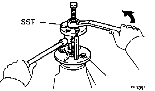
c. Using SST, remove the companion flange.
SST 09950-30011 (09951-03010, 09953-03010, 09954-03010, 09955-03030, 09956-03050)

9. REMOVE FRONT OIL SEAL
Using SST, remove the oil seal from the differential carrier.
SST 09308-10010

10. REMOVE FRONT BEARING AND BEARING SPACER
a. Using SST, remove the bearing from the drive pinion.
SST 09556-22010
If the front bearing is damaged or worn, replace the front bearing.
b. Remove the 2 washers and bearing spacer.
11. REMOVE DIFFERENTIAL CASE

a. Place matchmarks on the bearing cap and differential carrier.
b. Remove the 4 bolts and bearing cap.

c. Using SST and a plastic hammer, remove the 2 side bearing plate washers.
SST 09504-22011
HINT: Measure the plate washer thickness and note it down.
d. Remove the differential case with the bearing outer races from the carrier.
HINT: Tag the bearing outer races to show the location for reassembling.
12. REMOVE DRIVE PINION FROM DIFFERENTIAL CARRIER
Remove the drive pinion with the rear bearing.

13. REMOVE DRIVE PINION REAR BEARING
Using SST and a press, remove the bearing from the drive pinion.
SST 09950-00020
HINT: If the drive pinion or ring gear is damaged, replace them as a set.

14. REMOVE FRONT AND REAR BEARING OUTER RACES AND ADJUSTING WASHER
NOTICE: Do not remove the outer races except when replacing the bearings.
Using a brass bar and hammer, remove the outer races and adjusting washer from the carrier.
HINT: Measure the adjusting washer thickness and note it down.

15. REMOVE RING GEAR
a. Place matchmarks, on the ring gear and differential case.
b. Remove the 12 ring gear set bolts.
c. Using a plastic hammer, tap on the ring gear to separate it from the differential case.

16. CHECK DIFFERENTIAL CASE RUNOUT
a. Install the differential case in the differential carrier.
b. Using a dial indicator, measure the differential case runout.
Maximum case runout: 0.04 mm (0.0016 inch)
c. Remove the differential case.

17. REMOVE SIDE BEARINGS
Using SST, remove the 2 side bearings from the differential case.
SST 09950-40011 (09951-04010, 09952-04010, 09953-04020, 09954-04010, 09955-04061, 09957-04010, 09958-04011), 09950-60010 (09951-00480)
HINT: Fix the claws of SST to the notch in the differential case.

18. DISASSEMBLE DIFFERENTIAL CASE ASSEMBLY
a. Using a pin punch and hammer, remove the straight pin.
b. Remove the pinion shaft, 2 pinion gears, pinion gear thrust washers, side gears and side gear thrust washers from the differential case.
REPLACEMENT
REPLACE COMPANION FLANGE DUST DEFLECTOR

a. Using SST, a socket wrench and a press, remove the dust deflector.
SST 09950-00020

b. Using SST, a press and steel plate, install a new dust deflector.
SST 09523-36010
REASSEMBLY
1. ASSEMBLE DIFFERENTIAL CASE
a. Install the 2 thrust washers to the side gears.

b. Install the 2 side gears with the thrust washers, 2 pinion gears, 2 pinion gear thrust washers and pinion shaft.
HINT: Align the holes for the straight pin in the differential case and pinion shaft.

c. Using a dial indicator, measure the side gear backlash while holding one pinion gear toward the differential case.
Backlash: 0.05-0.20 mm (0.0020-0.0079 inch)
If the backlash is not within the specified value, replace the side gear thrust washer with one of an appropriate thickness.
HINT: Refer to the following table to select thrust washers which will ensure that the backlash is within the specified value.

Washer Thickness:

d. Using a pin punch and hammer, install the straight pin through the holes in the differential case and pinion shaft.
e. Using a chisel and hammer, stake the outside of the differential case pin hole.

2. INSTALL SIDE BEARINGS
Using SST and a press, install the 2 side bearings into the differential case.
SST 09950-60010 (09951-00480, 09951-00640) 09950-70010 (09951-07150)
3. INSTALL RING GEAR ON DIFFERENTIAL CASE
a. Clean the contact surfaces of the differential case and ring gear.

b. Heat the ring gear to about 100°C (212°F) in boiling water.
c. Carefully take the ring gear out of the boiling water.

d. After the moisture on the ring gear has completely evaporated, quickly install the ring gear to the differential case.
HINT: Align the matchmarks on the ring gear and differential case.
e. After the ring gear has cooled sufficiently, torque the set bolts to which thread lock has been applied.
Thread lock: Part No. 08833-00100, THREE BOND 1360K or equivalent.
Torque: 125 Nm (1,270 kgf-cm, 92 ft. lbs.)

4. INSPECT RING GEAR RUNOUT
a. Install the differential case into the carrier and install the plate washers to where there is no play in the bearing (See step 8).
b. Install the bearing cap (See step 11.).
c. Using a dial indicator, measure the runout of ring gear.
d. Remove the bearing caps and differential case.
Maximum runout: 0.05 mm (0.0020 inch)

5. INSTALL DRIVE PINION BEARING OUTER RACES AND ADJUSTING WASHER
a. Using SST and a press, install a new front bearing outer race to the carrier.
SST 09950-60020 (09951-00710), 09950-70010 (09951-07150)
b. Using SST and a press, install a new adjusting washer and a new rear bearing outer race to the carrier.
SST 09950-60020 (09951-00910), 09950-70010 (09951-07150)
HINT: First fit a washer with the same thickness as the washer which was removed, then after checking the tooth contact pattern, replace the washer with one of a different thickness if necessary.

6. INSTALL DRIVE PINION REAR BEARING
Using SST and a press, install the rear bearing onto the drive pinion.
SST 09506-35010
7. TEMPORARILY ADJUST DRIVE PINION PRELOAD
a. Install the drive pinion and front bearing.
HINT: After adjusting the ring gear tooth contact pattern, assemble the spacer, washers and oil seal.

b. Using SST, install the companion flange.
SST 09950-30011 (09951-03010, 09953-03010, 09954-03010, 09955-03030, 09956-03050)
c. Coat the threads of the nut with hypoid gear oil.
d. Adjust the drive pinion preload by tightening the companion flange nut.
HINT: Using SST to hold the flange, torque the nut.
SST 09330-00021
NOTICE: As there is no spacer, tighten the nut a little at a time and be careful not to overtighten it.
e. Using a torque wrench, measure the preload of the drive pinion using the backlash between the drive pinion and ring gear.
Preload (at starting):
New bearing 1.3-1.9 Nm (13-19 kgf-cm, 11.4-16.7 inch lbs.)
Reused bearing 0.5-0.8 Nm (5-8 kgf-cm, 4.3-6.9 inch lbs.)
8. INSTALL DIFFERENTIAL CASE IN CARRIER
a. Place the 2 bearing outer races on their respective bearings. Make sure the right and left races are not interchanged.
b. Install the differential case in the carrier.
9. ADJUST RING GEAR BACKLASH

a. Install the plate washer on the ring gear back side.
HINT: Make sure that the ring gear has backlash.

b. Tap on the ring gear with a plastic hammer so that the washer fits to the bearing.

c. Using a dial indicator, while holding the companion flange, measure the ring gear backlash.
Backlash (reference): 0.13-0.18 mm (0.0051-0.0071 inch)
d. Select a plate washer for back side ring gear using the backlash as a reference.

e. Select a ring gear teeth side plate washer so that there is no clearance between the outer race and case.
f. Remove the 2 plate washers and differential case.
g. Install the plate washer into the ring gear back side of the carrier.

h. Place the other plate washer onto the differential case together with the outer race, and install the differential case with the outer race into the carrier.
i. Tap on the ring gear with a plastic hammer so that the washers fit to the bearing.
j. Using a dial indicator, while holding the companion flange measure the ring gear backlash.
Backlash: 0.13-0.18 mm (0.0051-0.0071 inch)
If the backlash is not within the specified value, adjust it by either increasing or decreasing the thickness of washers on both sides by an equal amount.
HINT: There should be no clearance between the plate washer and the case. Make sure that there is a ring gear backlash.
10. ADJUST SIDE BEARING PRELOAD

a. Remove the ring gear teeth side plate washer and using a micrometer, measure the thickness.
b. Using the backlash as a reference, install a new washer 0.06-0.09 mm (0.0024-0.0035 inch) thicker than the washer removed.
HINT: Select a washer which can be pressed in 2/3 of the way with your finger.
c. Using a plastic hammer, install the plate washer.
d. Recheck the ring gear backlash.
Backlash: 0.13-0.18 mm (0.0051-0.0071 inch)
If the backlash is not within the specified value, adjust it by either increasing or decreasing the thickness of washers on both sides by equal amount.
HINT: The backlash will change by about 0.02 mm (0.0008 inch) corresponding to 0.03 mm (0.0012 inch) change in the plate washer.

Washer Thickness:
11. INSTALL BEARING CAP
a. Align the matchmarks on the cap and carrier.
b. Install and torque the 4 bolts.
Torque: 113 Nm (1,150 kgf-cm, 83 ft. lbs.)
12. MEASURE TOTAL PRELOAD
Using a torque wrench, measure the total preload with the teeth of the drive pinion and ring gear in contact.
Total preload (at starting):
Drive pinion preload plus 0.4-0.6 Nm (4-6 kgf-cm, 3.5-5.2 inch lbs.)

13. INSPECT TOOTH CONTACT BETWEEN RING GEAR AND DRIVE PINION
a. Coat 3 or 4 teeth at three different positions on the ring gear with red lead primer.
b. Hold the companion flange firmly and rotate the ring gear in both directions.

c. Inspect the teeth pattern.

If the teeth are not contacting properly, use the following table to select a proper washer for correction.

Washer Thickness:
14. REMOVE COMPANION FLANGE
15. REMOVE FRONT BEARING
16. INSTALL NEW BEARING SPACER, 2 WASHERS AND FRONT BEARING
a. Install a new bearing spacer and 2 washers, and place the front bearing.
b. Using SST and the companion flange, install the front bearing then remove the companion flange.
SST 09950-30011 (09951-03010, 09953-03010, 09954-03010, 09955-03030, 09956-03050)

17. INSTALL NEW OIL SEAL
a. Coat a new oil seal lip with MP grease.
b. Using SST and a plastic hammer, install the oil seal until its surface is flush with the differential carrier end.
SST 09316-12010, 09649-17010
HINT: Connect 2 SST with vinyl tape.

18. INSTALL COMPANION FLANGE
a. Place the companion flange.
b. Coat the threads of a new nut with hypoid gear oil.
c. Using SST to hold the flange, torque the nut.
SST 09330-00021
Torque: 147 Nm (1,500 kgf-cm, 109 ft. lbs.)
19. ADJUST DRIVE PINION PRELOAD
Using a torque wrench, measure the preload of the drive pinion using the backlash between the drive pinion and ring gear.
Preload (at starting):
New bearing 1.3-1.9 Nm (13-19 kgf-cm, 11.4-16.7 inch lbs.)
Reused bearing 0.5-0.8 Nm (5-8 kgf-cm, 4.3-6.9 inch lbs.)
If the preload is greater than the specified value, replace the bearing spacer.
If the preload is less than the specified value, retighten the nut with a force of 13 Nm (130 kgf-cm, 9 ft. lbs.) at a time until the specified preload is reached.
Torque: 451 Nm (4,600 kgf-cm, 333 ft. lbs.) or less
If the maximum torque is exceeded while retightening the nut, replace the bearing spacer and repeat the preload procedure. Do not loosen the pinion nut to reduce the preload.
20. CHECK TOTAL PRELOAD
Using a torque wrench, measure the total preload with the teeth of the drive pinion and ring gear in contact.
Total preload (at starting):
Drive pinion preload plus 0.4-0.6 Nm (4-6 kgf-cm, 3.5-5.2 inch lbs.)
21. CHECK RING GEAR BACKLASH
Using a dial indicator, measure the ring gear backlash.
Backlash: 0.13-0.18 mm (0.0051-0.0071 inch)
22. RECHECK TOOTH CONTACT BETWEEN RING GEAR AND DRIVE PINION (See step 13.)
23. CHECK COMPANION FLANGE RUNOUT
24. STAKE DRIVE PINION NUT