Rear Output Shaft
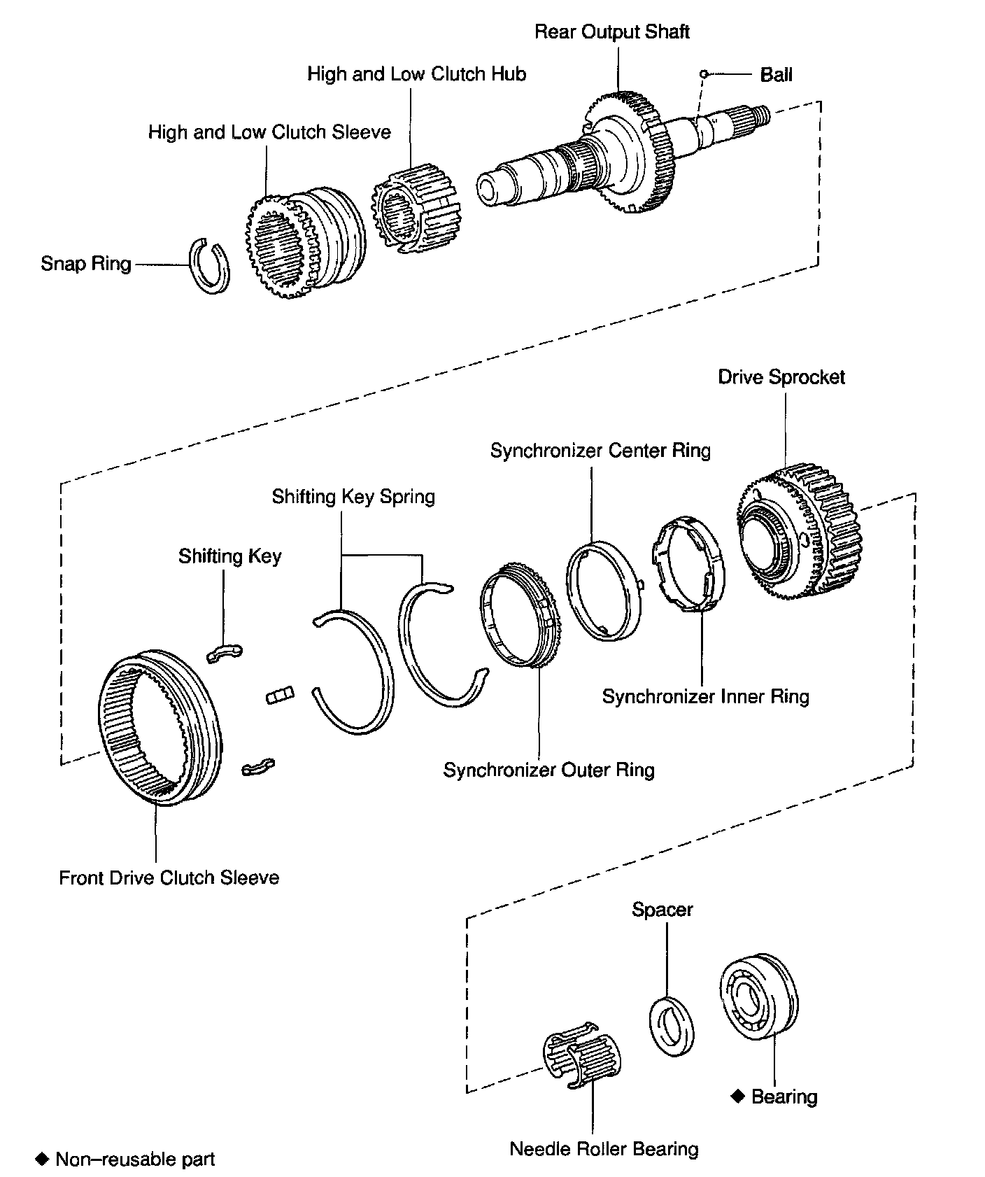
DISASSEMBLY

1. INSPECT DRIVE SPROCKET THRUST CLEARANCE
Using a feeler gauge, measure the drive sprocket thrust clearance.
Standard clearance: 0.10 - 0.25 mm (0.0039 - 0.0098 inch)
Maximum clearance: 0.25 mm (0.0098 inch)
If the clearance exceeds the maximum, replace the drive sprocket.
2. REMOVE HIGH AND LOW CLUTCH SLEEVE ASSEMBLY

a. Remove the clutch sleeve.
b. Using a snap ring expander, remove the snap ring.

c. Using a press, remove the clutch hub.
3. REMOVE BEARING, SPACER, DRIVE SPROCKET, SYNCHRONIZER OUTER, CENTER AND INNER RINGS AND FRONT DRIVE CLUTCH SLEEVE ASSEMBLY

a. Using SST and a press, remove the bearing.
SST 09555-55010

b. Remove the spacer and ball.
c. Remove the drive sprocket, needle roller bearing, synchronizer outer, center and inner rings.
d. Remove the front drive clutch sleeve assembly.
4. REMOVE 3 SHIFTING KEYS AND 2 KEY SPRINGS FROM FRONT DRIVE CLUTCH SLEEVE
INSPECTION

1. INSPECT REAR OUTPUT SHAFT
Using a micrometer, measure the rear output shaft journal surface outer diameter.
Minimum diameter:
Part A: 27.98 mm (1.1016 inch)
Part B: 36.98 mm (1.4561 inch)
If the outer diameter is less than the minimum, replace the rear output shaft.

2. INSPECT DRIVE SPROCKET RADIAL CLEARANCE
Using a dial indicator, measure the radial clearance between the sprocket and shaft with the needle roller bearing installed.
Standard clearance: 0.010 - 0.055 mm (0.0004 - 0.0022 inch)
Maximum clearance: 0.055 mm (0.0022 inch)
If the clearance exceeds the maximum, replace the drive sprocket, rear output shaft or needle roller bearing.

3. INSPECT FRONT DRIVE SHIFT FORK AND CLUTCH SLEEVE CLEARANCE
Using a feeler gauge, measure the clearance between the front drive shift fork and clutch sleeve.
Maximum clearance: 1.0 mm (0.039 inch)
If the clearance exceeds the maximum, replace the shift fork or clutch sleeve.

4. INSPECT HIGH AND LOW SHIFT FORK AND CLUTCH SLEEVE CLEARANCE
Using a feeler gauge, measure the clearance between the high and low shift fork and clutch sleeve.
Maximum clearance: 1.0 mm (0.039 inch)
If the clearance exceeds the maximum, replace the shift fork or clutch sleeve.
REASSEMBLY
1. INSTALL FRONT DRIVE CLUTCH SLEEVE ONTO REAR OUTPUT SHAFT

a. Install the front drive clutch sleeve onto the rear output shaft.
NOTICE: Make sure that the clutch sleeve is installed facing in the correct direction.

b. Install the 3 shifting keys and 2 springs.
NOTICE: Install the key springs positioned so that their end gaps are not in line.
2. INSTALL SYNCHRONIZER OUTER, CENTER AND INNER RINGS, DRIVE SPROCKET, SPACER AND BEARING
a. Apply gear oil to the rear output shaft and needle roller bearing.

b. Install the synchronizer outer ring to the rear output shaft.
NOTICE: Align the slots of the synchronizer outer ring with the shifting keys.
c. Install the synchronizer center and inner rings to the rear output shaft.
NOTICE: Align the slots of the synchronizer outer with those of inner rings.

d. Install the needle roller bearing to the rear output shaft.
e. Install the drive sprocket to the rear output shaft.
NOTICE: Align the holes in the drive sprocket with the protrusions of the synchronizer center ring.
f. Install the spacer to align it with the ball.

g. Using SST and a press, install a new bearing with the outer race snap ring groove toward the rear.
SST 09316-60011 (09316-00011, 09316-00071)

3. INSPECT DRIVE SPROCKET THRUST CLEARANCE
Using a feeler gauge, measure the drive sprocket thrust clearance.
Standard clearance: 0.10 - 0.25 mm (0.0039 - 0.0098 inch)

4. INSERT HIGH AND LOW CLUTCH HUB ONTO CLUTCH SLEEVE
NOTICE: Make sure that the high and low clutch hub is installed facing in the correct direction.

5. INSTALL HIGH AND LOW CLUTCH HUB ASSEMBLY
Using a press, install the high and low clutch hub assembly.


6. INSTALL SNAP RING
Select a snap ring that allows minimum axial play and install it to the shaft.