Transfer Assembly

DISASSEMBLY
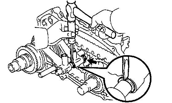
1. REMOVE VEHICLE SPEED SENSOR ASSEMBLY
a. Remove the bolt and vehicle speed sensor assembly.
b. Remove the O-ring from the vehicle speed sensor assembly.
c. Remove the clip and vehicle speed sensor driven gear from the vehicle speed sensor assembly.
2. REMOVE 3 PLUGS AND GASKETS FROM FRONT CASE
3. REMOVE PROTECTOR
Remove the 4 bolts and protector.

4. REMOVE FRONT BEARING RETAINER
a. Remove the 5 bolts.
b. Using a plastic hammer, tap the front bearing retainer and remove it.
5. REMOVE UPPER COVER AND OIL DEFLECTOR
Remove the 4 bolts, upper cover, 2 gaskets and oil deflector.
6. REMOVE FRONT COMPANION FLANGE
a. Using a chisel and hammer, loosen the staked part of the front companion flange lock nut.

b. Using SST, hold the front companion flange and remove the front companion flange lock nut.
SST 09330-00021

c. Using SST, remove the front companion flange.
SST 09950-40011 (09951-04020, 09952-04010, 09953-04030, 09954-04010, 09955-04051, 09957-04010, 09958-04011)
7. REMOVE REAR COMPANION FLANGE
Remove the rear companion flange in the same way as the front companion flange.

8. REMOVE EXTENSION HOUSING
a. Remove the 5 bolts.
b. Using a plastic hammer, tap the extension housing and remove it.
9. REMOVE VEHICLE SPEED SENSOR DRIVE GEAR
a. Remove the 2 output washers and vehicle speed sensor drive gear.
b. Using a magnetic finger, remove the ball from the rear output shaft.

10. SEPARATE FRONT CASE AND REAR CASE
a. Remove the 12 bolts and 2 clamps.
b. Using a plastic hammer, tap the front case and rear case and separate them.
11. REMOVE SHIFT FORK SHAFT

a. Using a hexagon wrench (6 mm), remove the 2 straight screw plugs, springs and balls from the front drive and high and low shift forks.

b. Using 2 screwdrivers and a hammer, tap out the 2 snap rings from the shift fork shaft.

c. Remove the bolt and shift fork shaft stopper.

d. To pullout the shift fork shaft, shift the front drive and high and low shift forks to the positions as shown in the illustration.
e. Pull out the shift fork shaft.

f. Using a magnetic finger, remove the 2 straight pins from the front drive and high and low shift forks.
12. REMOVE REAR OUTPUT SHAFT ASSEMBLY, DRIVEN SPROCKET ASSEMBLY, CHAIN AND FRONT DRIVE AND HIGH AND LOW SHIFT FORKS

a. Using 2 screwdrivers and a hammer, tap out the snap ring from the shift fork shaft of the actuator assembly.
HINT: Remove only the snap ring on the front side of the shift fork shaft.

b. Using a snap ring expander, remove the snap ring.

c. Mount the rear case in a vise.
d. Using a plastic hammer, carefully tap the rear case, and remove the rear output shaft assembly, driven sprocket assembly, chain and front drive and high and low shift forks with an assembly.
e. Remove the driven sprocket assembly, chain and front drive and high and low shift forks from the rear output shaft assembly.
13. REMOVE ACTUATOR ASSEMBLY

a. Using 2 screwdrivers and a hammer, remove the snap ring.
b. Remove the 3 bolts and actuator assembly.

c. Remove the O-ring, transfer 4WD position switch and transfer L4 position switch and 2 gaskets from the actuator assembly.

14. REMOVE SEPARATOR WITH OIL STRAINER AND MAGNET
Remove the 3 bolts, separator with the oil strainer and magnet.

15. REMOVE OIL PUMP BODY ASSEMBLY
Remove the 3 bolts and oil pump body assembly.
16. REMOVE OIL PUMP DRIVE GEAR
17. REMOVE PLANETARY GEAR ASSEMBLY WITH INPUT SHAFT ASSEMBLY

a. Using a snap ring expander, remove the snap ring.

b. Pull out the planetary gear assembly with the input shaft assembly.
18. REMOVE LOW GEAR SPLINE PIECE

a. Using a screwdriver, remove the snap ring.

b. Remove the low gear spline piece.

19. REMOVE NEEDLE ROLLER BEARING FROM INPUT SHAFT ASSEMBLY
20. REMOVE INPUT GEAR STOPPER AND THRUST WASHER

a. Using a snap ring expander, remove the snap ring.

b. Remove the input gear stopper, ball and thrust washer.

21. REMOVE INPUT SHAFT ASSEMBLY, THRUST BEARING AND RACE
22. REMOVE PLANETARY RING GEAR

a. Using a screwdriver, remove the snap ring.

b. Remove the head screw plug, spring and pin.

c. Remove the planetary ring gear.


23. INSPECT SWITCH
Check that continuity exists between terminals as shown.
If operation is not as specified, replace the switch.
REASSEMBLY
HINT: Coat all of the sliding and rotating surface with gear oil before reassembly.
1. INSTALL PLANETARY RING GEAR

a. Install the planetary ring gear.
NOTICE: Make sure that the planetary ring gear is installed facing in the correct direction.

b. Install the pin and spring.
c. Apply sealant to the head screw plug threads.
Sealant: Part No. 08833-00080, THREE BOND 1344, LOCTITE 242 or equivalent
d. Install the head screw plug.
Torque: 19 Nm (190 kgf-cm, 14 ft. lbs.)

e. Using a screwdriver, install the snap ring.
NOTICE: Make sure the end gap of the snap ring is not aligned with the upper side of the case.

2. INSTALL INPUT SHAFT ASSEMBLY, THRUST BEARING AND RACE
3. INSTALL THRUST WASHER AND INPUT GEAR STOPPER

a. Install the thrust washer, ball and input gear stopper.
HINT: Apply gear oil to the input gear stopper and thrust washer.


b. Select a snap ring that allows 0.05 - 0.15 mm (0.0020 - 0.0059 inch) axial play.

c. Using a snap ring expander,, install a snap ring.

4. INSTALL NEEDLE ROLLER BEARING TO INPUT SHAFT ASSEMBLY
HINT: Apply gear oil to the needle roller bearing.
5. INSTALL LOW GEAR SPLINE PIECE

a. Install the low gear spline piece.

b. Using a screwdriver, install the snap ring.
NOTICE: Make sure the end gap of the snap ring is not aligned with the cutout portion of the planetary carrier.
6. INSTALL PLANETARY GEAR ASSEMBLY WITH INPUT SHAFT ASSEMBLY

a. Install the planetary gear assembly with the input shaft assembly.
HINT: If necessary, heat the front case to about 50 - 80°C (122 - 176°F).

b. Using a snap ring expander, install the snap ring.
HINT: Check that the planetary gear and input shaft assembly turn lightly.
7. INSTALL OIL PUMP DRIVE GEAR

8. INSTALL OIL PUMP BODY ASSEMBLY
Install the oil pump body assembly with the 3 bolts.
Torque: 7.5 Nm (80 kgf-cm, 69 inch lbs.)

9. INSTALL MAGNET AND SEPARATOR WITH OIL STRAINER
a. Install the magnet to the front case.
b. Install the separator with oil strainer with the 3 bolts.
Torque: 7.5 Nm (80 kgf-cm, 69 inch lbs.)
10. INSTALL ACTUATOR ASSEMBLY

a. Install a new O-ring, 2 new gaskets, transfer 4WD position switch and transfer L4 position switch to the actuator assembly.
Torque: 37 Nm (380 kgf-cm, 27 ft. lbs.)
HINT: Coat a new O-ring with gear oil.
b. Install the actuator assembly with the 3 bolts.
Torque: 20 Nm (200 kgf-cm, 14 ft. lbs.)

c. Using a screwdriver and hammer, drive in the snap ring to the shift fork shaft of the actuator assembly.
HINT: Install only the snap ring on the rear side of the shift fork shaft.
11. INSTALL REAR OUTPUT SHAFT ASSEMBLY, DRIVEN SPROCKET ASSEMBLY, CHAIN AND FRONT DRIVE AND HIGH AND LOW SHIFT FORKS

a. Install the driven sprocket assembly, chain and front drive and high and low shift forks to the rear output shaft assembly.
NOTICE: Make sure that the front drive and high and low shift forks are installed facing in the correct direction.

b. Mount the rear case in a vise.
c. Install the rear output shaft assembly, driven sprocket assembly, chain and front drive and high and low shift forks to the rear case with an assembly.
NOTICE: Do not let the clutch sleeve and shifting key drop.
HINT: If necessary, heat the rear case to about 50 - 80°C (122 - 176°F).

d. Using a snap ring expander, install the snap ring.

e. Using a screwdriver and hammer, drive in the snap ring to the shift fork shaft of the actuator assembly.
HINT: Check that the rear output shaft assembly and driven sprocket assembly turn lightly.
12. INSTALL SHIFT FORK SHAFT

a. Using a magnetic finger, install the 2 straight pins to the front drive and high and low shift forks.

b. To push into the shift fork shaft, shift the front drive and high and low shift forks to the positions as shown in the illustration.
c. Push into the shift fork shaft.
NOTICE: Make sure that the shift fork shaft is installed facing in the correct direction.

d. Install the shift fork shaft stopper with the bolt.
Torque: 19 Nm (190 kgf-cm, 14 ft. lbs.)
e. Using a screwdriver and hammer, drive in the 2 snap rings to the shift fork shaft.

f. Install the 2 balls and springs to the front drive and high and low shift forks.
g. Apply sealant to the straight screw plug threads.
Sealant: Part No. 08933-00080, THREE BOND 1344, LOCTITE 242 or equivalent
h. Using a hexagon wrench (6 mm), install the 2 straight screw plugs to the front drive and high and low shift forks.
Torque: 19 Nm (190 kgf-cm, 14 ft. lbs.)
13. REASSEMBLE FRONT AND REAR CASE
HINT: Remove any FIPG material and be careful not to drop oil on the contacting surfaces of the rear case.

a. Apply FIPG to the rear case as shown in the illustration.
FIPG: Part No. 08826-00090, THREE BOND 1281 or equivalent

b. Install the 2 clamps and reassemble the front and rear case with the 12 bolts.
Torque: 28 Nm (285 kgf-cm, 21 ft. lbs.)
14. INSTALL VEHICLE SPEED SENSOR DRIVE GEAR
a. Install the ball to the rear output shaft.
b. Install the vehicle speed sensor drive gear and 2 output washers.
15. INSTALL EXTENSION HOUSING HINT:
Remove any FIPG material and be careful not to drop oil on the contacting surfaces of the extension housing.

a. Apply FIPG to the extension housing as shown in the illustration.
FIPG: Part No. 08826-00090, THREE BOND 1281 or equivalent
b. Apply sealant to the bolt threads.
Sealant: Part No. 08833-40080, THREE BOND 1344, LOCTITE 242 or equivalent

c. Install the extension housing with the 5 bolts.
Torque: 12 Nm (120 kgf -cm, 9 ft. lbs.)

16. INSTALL FRONT COMPANION FLANGE
a. Install the front companion flange to the input shaft.
b. Using SST, hold the front companion flange, and install a new front companion flange lock nut.
SST 09330-00021
Torque: 118 Nm (1,200 kgf-cm, 87 ft. lbs.)
c. Stake the front companion flange lock nut.
17. INSTALL REAR COMPANION FLANGE
Install the rear companion flange in the same way as the front companion flange.
18. INSTALL OIL DEFLECTOR AND UPPER COVER
Install 2 new gaskets, oil deflector and upper cover with the 4 bolts.
Torque: 18 Nm (185 kgf-cm, 13 ft. lbs.)

19. INSTALL FRONT BEARING RETAINER HINT:
Remove any FIPG material and be careful not to drop oil on the contacting surfaces of the front bearing retainer.
a. Apply FIPG to the front bearing retainer as shown in the illustration.
FIPG: Part No. 08826-00090, THREE BOND 1281 or equivalent
b. Apply sealant to the bolt threads.
Sealant: Part No. 08833-00080, THREE BOND 1344, LOCTITE 242 or equivalent

c. Install the front bearing retainer with the 5 bolts.
Torque: 11 Nm (115 kgf-cm, 8 ft. lbs.)
20. INSTALL PROTECTOR
Install the protector with the 4 bolts.
Torque: 18 Nm (185 kgf-cm, 13 ft. lbs.)
21. INSTALL 3 PLUGS AND NEW GASKETS TO FRONT CASE
Torque: 37 Nm (380 kgf-cm, 27 ft. lbs.)
22. INSTALL VEHICLE SPEED SENSOR ASSEMBLY
a. Install the vehicle speed sensor driven gear to the vehicle speed sensor assembly with the clip.
b. Install a new O-ring to the vehicle speed sensor assembly.
HINT: Coat a new O-ring with gear oil.
c. Install the vehicle speed sensor assembly with the bolt.
Torque: 11 Nm (115 kgf-cm, 8 ft. lbs.)