Control Module: Testing and Inspection
1. INSPECT THROTTLE POSITION SENSOR SIGNAL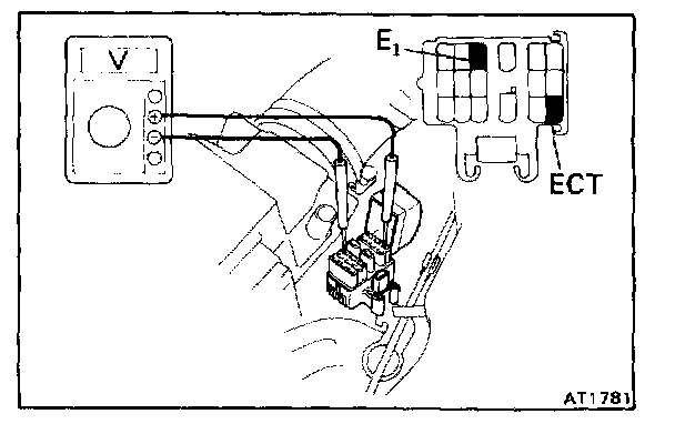
a. Turn the ignition switch to ON. Do not start the engine.
b. Connect a voltmeter to the terminals ECT and E(1) of the service connector.
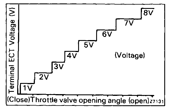
c. While slowly depressing the accelerator pedal, check that terminal ECT voltage rises in sequence.
If the voltage is in proportion to the throttle opening angle and does not change, there is a malfunction with the throttle position sensor or circuit.
2. INSPECT BRAKE SIGNAL
a. Depress the accelerator pedal until the terminal ECT indicates 8 V.
b. Depress the brake pedal and check the voltage reading from the terminal ECT.
Brake pedal depressed 0 V
Brake pedal released 8 V
If not as indicated, there is a malfunction in either the stop light switch or circuit.
3. INSPECT EACH UP SHIFT POSITION
a. Warm up the engine.
Coolant temperature: 80 °C (176 °F)
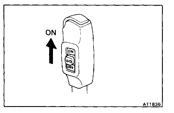
b. Turn the OD switch to "ON".
c. Place the pattern select switch in "Normal" and the shift selector into the D range.
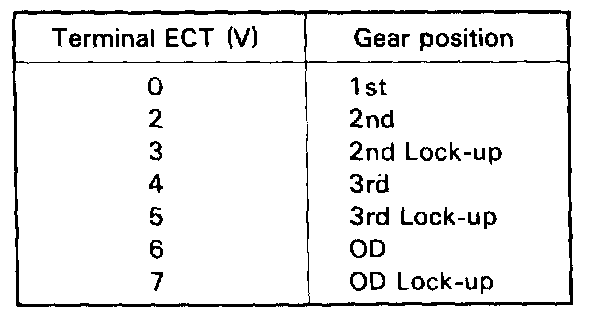
d. During a road test (above 10 kph or 6 mph) check that voltage at the terminal ECT is as indicated below for each up-shift position.
e. If the voltage rises from 0 V to 7 V in the sequence shown, the control system is okay.
f. The voltage could rise anywhere between 0 V - 8 V before the vehicle reaches 10 kph (6 mph), the voltmeter indicates the current gear.
NOTE: Determine the gear position by a light shock or change in engine rpm when shifting.