Recall - Oxygen Sensor Replacement
TO:ALL TOYOTA DEALER PRINCIPALS, SERVICE MANAGERS, PARTS MANAGERS
SUBJECT:
SPECIAL SERVICE CAMPAIGN -- S02 (1993 and 1994 LAND CRUISER O2 SENSOR)
Toyota will initiate a Special Service Campaign to replace the O2 sensors on 1993 and 1994 model year Toyota Land Cruisers.
Toyota has determined that the oxygen sensor heater wire on the vehicle may have an open circuit due to repeated thermal stress, causing the Malfunction Indicator Lamp (MIL) to illuminate.
Please be sure to perform the necessary inspection and/or repair on any vehicles acquired in your inventory prior to sale or lease of the vehicle.
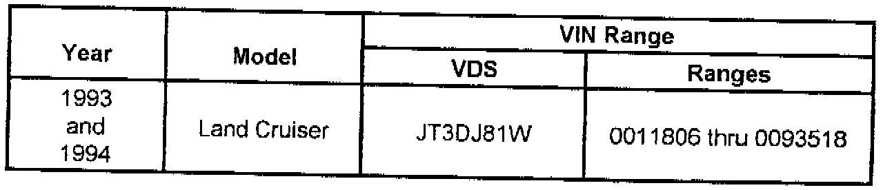
1. Owner Notification Letter Mailing Date
August, 1995 (copy included)
2. Identification of Involved Vehicles
NOTE:
Although the involved vehicles are within the above VIN ranges; not all vehicles in these ranges were imported into the U.S.
Should you be contacted by the owner of an involved vehicle who has not yet received a notification, please verify eligibility by referring to the VIN range and perform the necessary modification.
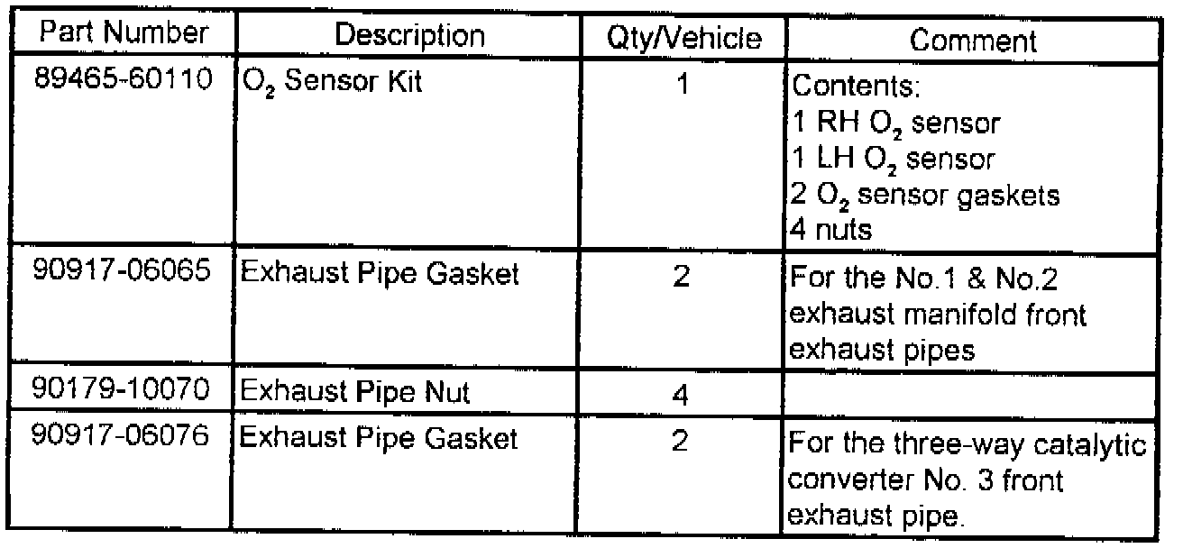

3. Repair Procedures
Refer to the Technical Instructions.
4. Parts Ordering
Necessary parts must be ordered from your facing Parts Distribution Center. In order to avoid excessive parts orders and maintain adequate parts inventory, your initial parts order should not exceed 10% of the number of involved vehicles listed in your PMA Dealer/Owner list (SSC S02).
Reimbursement Procedures
Submit Special Service Campaign claims following the procedures described in the Toyota Warranty Policy & Procedures Manual.
NOTE:
The above flat rate time includes 0.1 flat rate hour for administrative expense. Please review this entire package with your Service and Parts staff to familiarize them with the proper step-by-step procedure and implement this Special Service Campaign to ensure customer satisfaction.
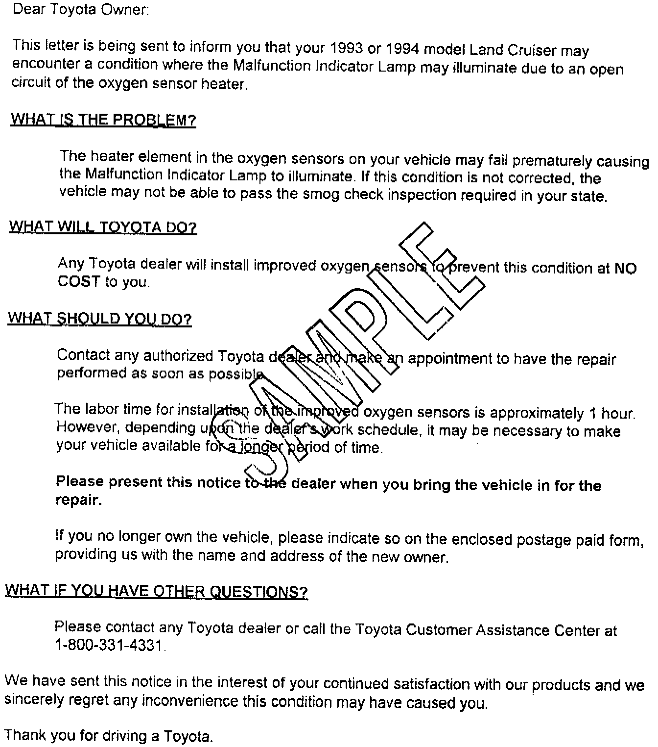
SSC S02 - TOYOTA LAND CRUISER OXYGEN SENSOR SPECIAL SERVICE CAMPAIGN NOTICE
TECHNICAL INSTRUCTIONS FOR SPECIAL SERVICE CAMPAIGN S02
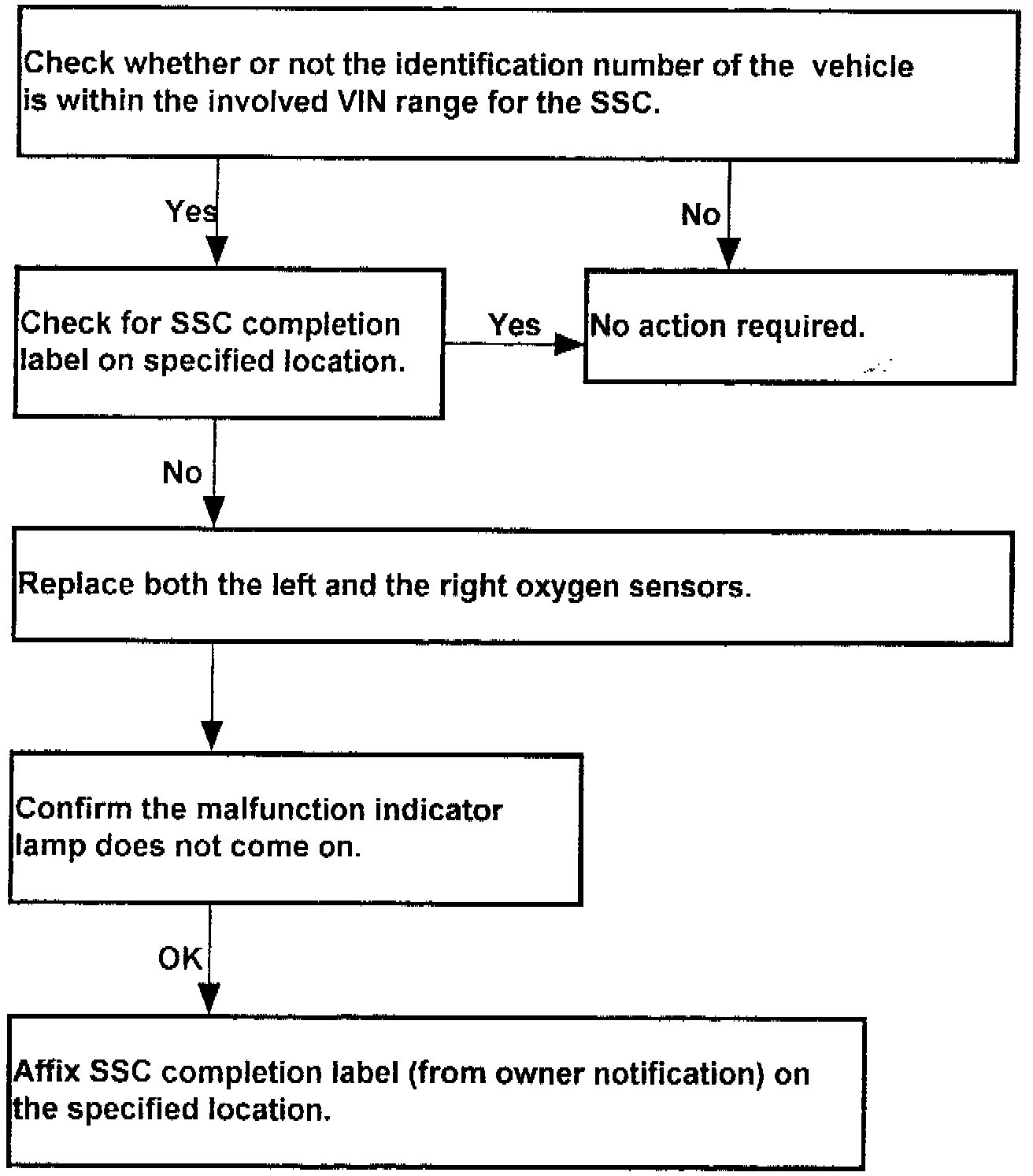
I. OPERATION FLOW CHART
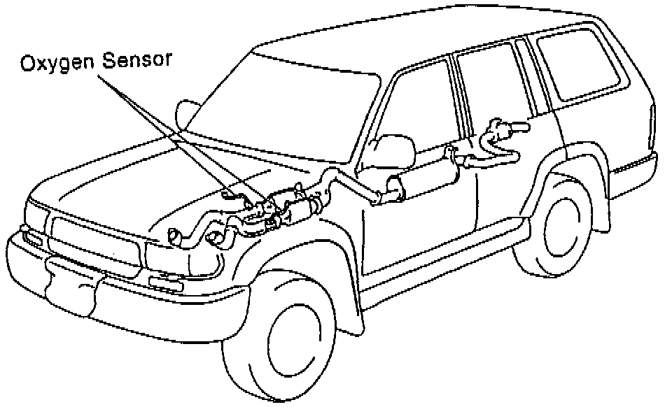
II. LOCATION OF AFFECTED PARTS
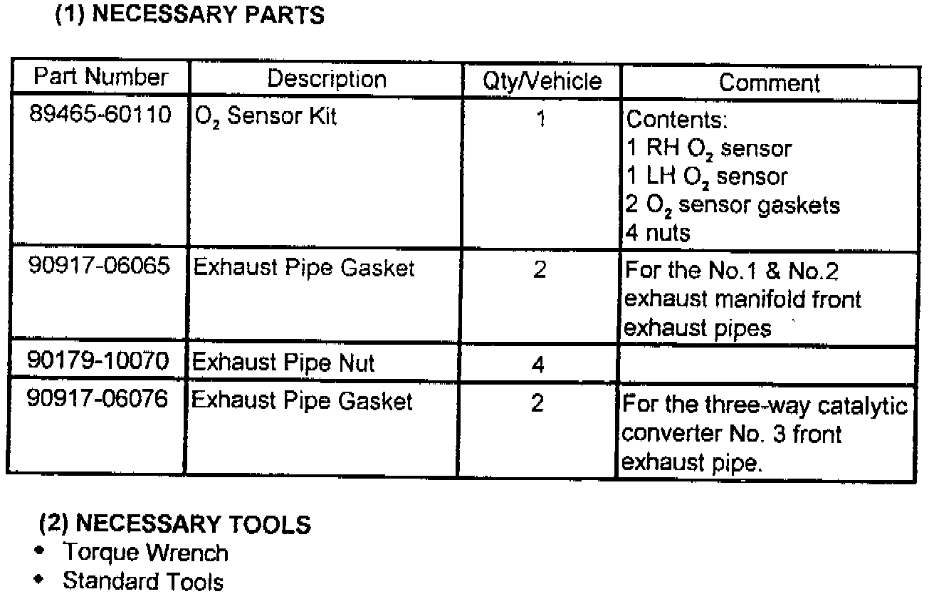
III. PREPARATION
IV. WORK PROCEDURE
1. CHECK THE IGNITION KEY IS EITHER AT OFF POSITION OR IS PULLED OUT.
2. JACK UP THE VEHICLE.
3. DISCONNECT BOTH OXYGEN SENSOR CONNECTORS
(a) For the right-side oxygen sensor, remove the clip and disconnect the oxygen sensor from the body.
4. REMOVE FRONT EXHAUST PIPE.
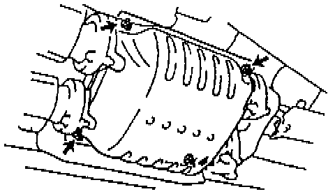
(a) Remove the 4 nuts and the lower converter insulator cover.
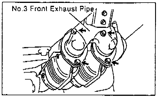
(b) Remove the 4 bolts, 2 nuts, retainer and disconnect the three-way catalytic converter from the No. 3 front exhaust pipe assembly.
NOTE:
If corrosion renders the exhaust bolts and nuts non-reusable, following are the necessary part numbers:
Bolt: 91511-61035, Nut: 94180-41000.
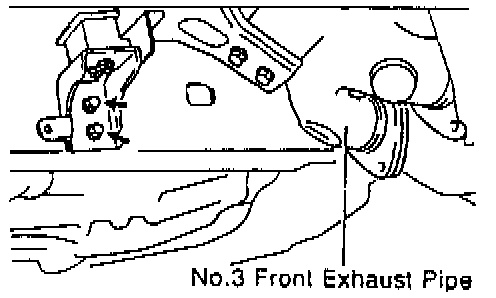
(c) Remove the 2 bolts to disconnect the No. 3 front exhaust pipe assembly from the frame.
(d) Loosen the clamp bolt and disconnect the clamp from the No. 1 support bracket.
NOTE:
Clamp bolt: 91621-60835.
(e) Remove the 2 nuts and the No. 2 front exhaust pipe assembly from the No. 2 exhaust manifold.
NOTE:
Manifold stud bolt: 90126-10006.

(f) Remove the gasket from the No. 2 front exhaust pipe assembly.
(g) Remove the upper converter insulator cover
(h) Remove the 2 nuts and the No. 1 front exhaust pipe assembly from the No. 1 exhaust manifold.
(i) Remove the gasket from the No. 1 front exhaust pipe assembly.
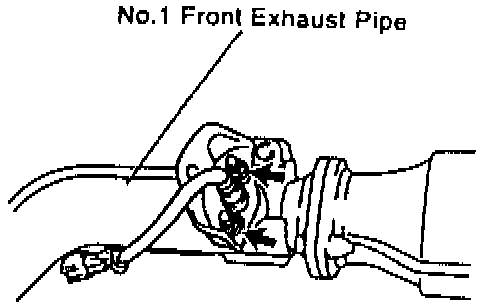
5. REMOVE OXYGEN SENSOR
(a) Remove the 2 nuts, oxygen sensor cover, oxygen sensor and gasket from the No. 1 front exhaust pipe assembly.
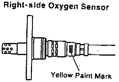
(b) Install a new gasket, right-side oxygen sensor (indicated by a yellow paint mark as shown in the illustration.), and the oxygen sensor cover to the No. 1 front exhaust pipe assembly with 2 new nuts.
Torque: 20 N-m (200 kg-cm, 14 ft-lb)
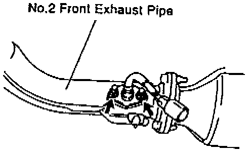
(c) Remove the 2 nuts, oxygen sensor and gasket from the No.2 front exhaust pipe assembly.
(d) Install a new gasket and left-side oxygen sensor to the No. 2 front exhaust pipe assembly with 2 new nuts.
Torque: 20 N-m (200 kg-cm, 14 ft-lb)
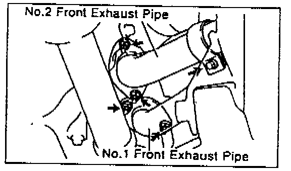
6. REINSTALL FRONT EXHAUST PIPE
(a) Install a new gasket to the No. 1 front exhaust pipe assembly.
(b) Reinstall the No. 1 front exhaust pipe assembly to the No. 1 exhaust manifold with 2 new nuts.
Torque: 62 N-m, (630 kg-cm, 46 ft-lb)
(c) Reinstall the upper converter insulator cover.
(d) Install a new gasket to the No. 2 front exhaust pipe assembly.
(e) Reinstall the No. 2 front exhaust pipe assembly to the No.2 exhaust manifold with 2 new nuts.
Torque: 62 N-m (630 kg-cm, 46 ft-lb)
(f) Clamp the No. 2 front exhaust pipe to the No. 1 support bracket with the clamp bolt.
Torque: 19 N-m (195 kg-cm, 14 ft-lb)
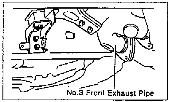
(g) Tighten the 2 bolts as shown in the illustration.
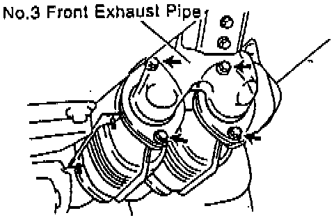
(h) Install 2 new gaskets to the No. 3 front exhaust pipe assembly and reconnect that to the three-way catalytic converter with 4 bolts 2 nuts and retainer,

(i) Reinstall the lower converter insulator cover with 4 nuts.
Torque: 11 N-m(110 kg-cm, 8 ft-lb)
7. RECONNECT BOTH OXYGEN SENSOR CONNECTORS
(a) For the right-side oxygen sensor, reinstall the clip and reconnect the oxygen sensor to the body.
8. USE THE IGNITION KEY TO START THE VEHICLE, MAKE SURE THAT THE MALFUNCTION INDICATOR LAMP DOES NOT ILLUMINATE.
9. SSC COMPLETION LABEL INSTALLATION
(a) After completing repair and before returning vehicle to the owner, a SSC completion label that is enclosed in the owner's notification must be affixed to the left front door hinge post near the check strap.
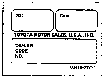
(b) The label is to be filled out as follows:
^ Write in SSC S02
^ Write in date of repair
^ Write in your Dealer Code
(c) Additional SSC completion labels, in sheets of 50 (P/N 00410-01917), may be ordered through the non-parts system on a 1450 order form or through the TDN system.