Transmission Control Systems: Description and Operation
HYDRAULIC CONTROL SYSTEMThe hydraulic control system is composed of the oil pump, the valve body. the solenoid valves, the accumulators, the clutches and brakes as well as the fluid passages which connect all of these components.
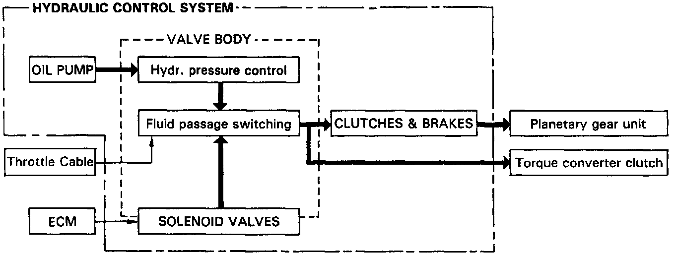
Based on the hydraulic pressure created by the oil pump, the hydraulic control system governs the hydraulic pressure acting on the torque converter clutch, clutches and brakes in accordance with the vehicle driving conditions.
There are three solenoid valves on the valve body.
The No.1 and No.2 solenoid valves are turned ON and OFF by signals from the ECM to operate the shift valves and change the gear shift position.
The lock-up solenoid valve is operated by signals from the ECM to engage or disengage the lock-up clutch of the torque converter clutch.
ELECTRONIC CONTROL SYSTEM
The electronic control system for controlling the shift timing and the operation of the lock-up clutch is composed of the following three parts:
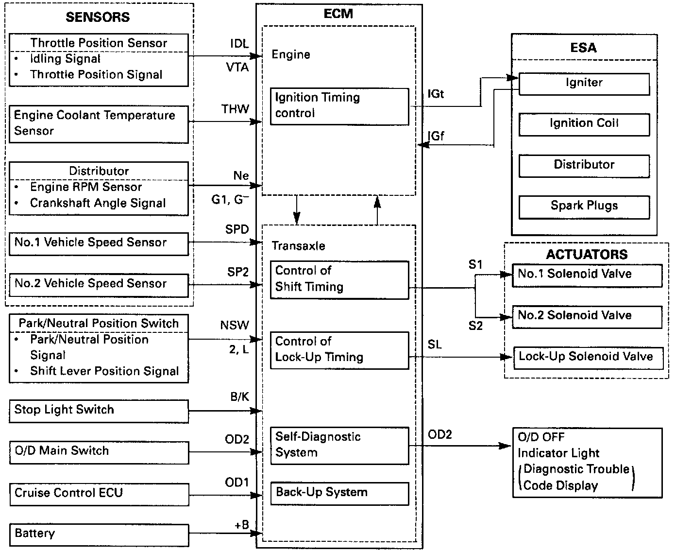
^ Sensors: These sense the vehicle speed and throttle position and send this data to the ECM in the form of electronic signals.
^ ECM: This determines the shift and lock-up timing based upon the signals from the sensors.
^ Actuators: Solenoid valves divert hydraulic pressure from one circuit of the hydraulic control unit to another, thus controlling shifting and lock-up timing.
SELF DIAGNOSTIC SYSTEM
A self-diagnosis function is built into the electrical control system.
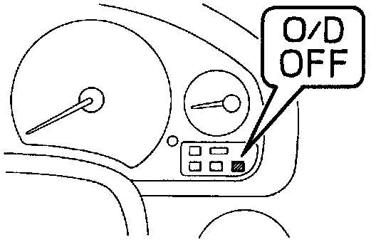
Warning is indicated by the ""O/D OFF"" indicator.
- If a malfunction occurs within the speed sensors or solenoids, the "O/D OFF" indicator light will blink to warn the driver.
- A malfunction in the lock-up solenoid circuit will produce a fault code, but the warning indicator will not flash.
HINT: Warning and diagnostic codes can be read only when the overdrive switch is ON (in). When the overdrive switch is in the OFF (out) position, the "O/D OFF" light is illuminated and will not flash.
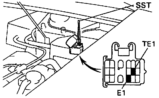
The diagnostic code can be read by the number of blinks of the "O/D OFF" indicator when terminals TE1 and E1 are short-circuited.
The throttle position sensor and brake signals do not generate fault codes but inspection can be made by checking the voltage at terminal TT of the check connector.
Voltage Output From Terminal TT Of DLC1 Should Step Up In 1 Volt Increments As The Transaxle Shifts Up:
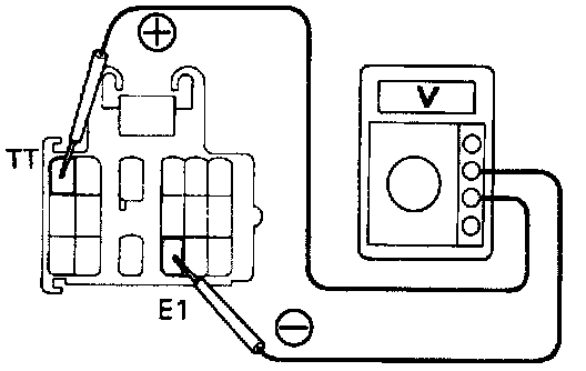
The signals to each gear can be checked by measuring the voltage at terminal TT of the check connector while driving.
The diagnostic (malfunction) code is retained in memory by the ECM and is not canceled out when the engine is turned off.
Remove The (15 Amp) EFI Fuse To Clear The Malfunction Codes:
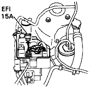
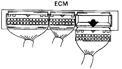
After repair, it is necessary to turn the ignition switch OFF and remove the (15 A) EFI fuse or disconnect the ECM connector to cancel out the diagnostic trouble codes.
HINT: Low battery voltage will cause faulty operation of the diagnosis system. Therefore, always check for proper battery voltage before troubleshooting.