Manifold Pressure/Vacuum Sensor: Testing and Inspection
MAP Sensor Circuit - Schematic View:
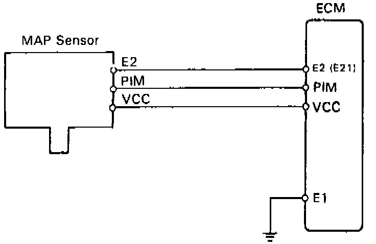
1. Remove MAP sensor.
2. Inspect power source voltage of Map sensor.
a. Disconnect the MAP sensor connector.
b. Turn the ignition switch ON.
Testing The MAP Sensor:
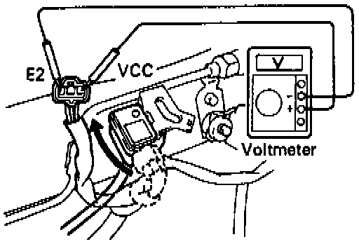
c. Using a voltmeter, measure the voltage between terminals VCC and E2 of the MAP sensor connector.
Voltage: 4 - 6V
d. Reconnect the MAP sensor connector.
3. Inspect power output of Map sensor.
a. Turn the ignition switch ON.
b. Disconnect the vacuum hose on the air intake chamber side.
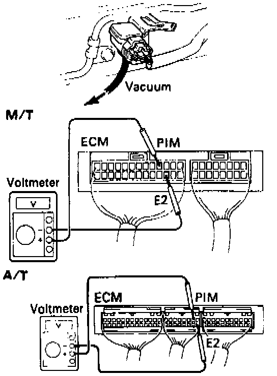
c. Connect a voltmeter to terminals PIM and E2 of the ECM, and measure the output voltage under ambient atmospheric pressure.
MAP Sensor Value Chart:
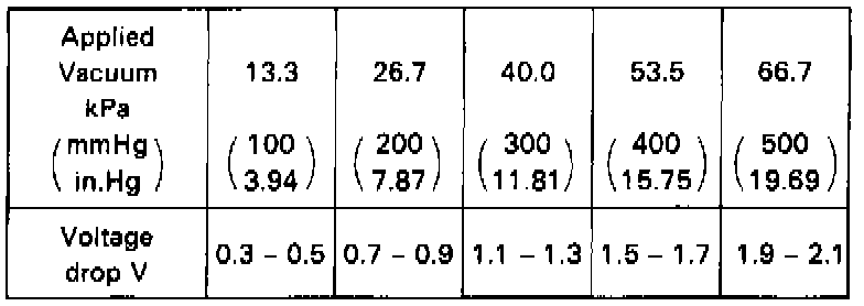
d. Apply vacuum to the MAP sensor in 13.3 kPa (100 mm Hg.3.94 in.Hg) segments to 66.7 kPa (500 mmHg, 19.69 in.Hg).
e. Measure the voltage drop from step (c) above for each segment.
f. Reconnect the vacuum hose to the air intake chamber.