Technician Safety Information
PRECAUTIONS FOR VEHICLES EQUIPPED WITH SUPPLEMENTAL RESTRAINT SYSTEM (SRS)The 1995 LAND CRUISER is equipped with an SRS (Supplemental Restraint System), such as the driver airbag, front passenger airbag and seat belt pretensioners.
Failure to carry out service operations in the correct sequence could cause the supplemental restraint system to unexpectedly deploy during servicing, possibly leading to a serious accident.
Further, if a mistake is made in servicing the supplemental restraint system, it is possible the SRS may fail to operate when required. Before servicing (including removal or installation of parts, inspection or replacement), be sure to read the following items carefully, then follow the correct procedure described in this manual.
1. Malfunction symptoms of the supplemental restraint system are difficult to confirm, so the diagnostic trouble codes become the most important source of information when troubleshooting. When troubleshooting the supplemental restraint system, always inspect the diagnostic trouble codes before disconnecting the battery.
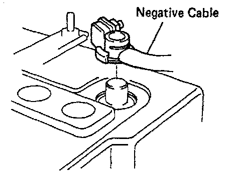
2. Work must be started after 90 seconds from the time the ignition switch is turned to the LOCK position and the negative (-) terminal cable is disconnected from the battery.
(The supplemental restraint system is equipped with a back-up power source so that if work is started within 90 seconds of disconnecting the negative (-) terminal cable from the battery, the SRS may deploy.)
When the negative (-) terminal cable is disconnected from the battery, memory of the clock and audio systems will be cancelled. So before starting work, make a record of the contents memorized by the audio memory system. When work is finished. reset the audio systems as before and adjust the clock.
This vehicle has power tilt and power telescopic steering, power seat, power outside rear view mirror and power shoulder belt anchorage, which are all equipped with memory function, it is not possible to make a record of the memory contents.
So when the work is finished, therefore it will be necessary to explain this fact to the customer, and ask the customer to adjust the features and reset the memory.
To avoid erasing the memory of each memory system, never use a back-up power supply from outside the vehicle.
3. Even in cases of a minor collision where the SRS does not deploy, the steering wheel pad and front airbag sensors should be inspected.
4. Never use SRS parts from another vehicle. When replacing parts, replace them with new parts.
5. Before repairs, remove the airbag sensors if shocks are likely to be applied to the sensors during repairs.
6. Never disassemble and repair the front airbag sensors, center airbag sensor assembly, steering wheel pad or front passenger airbag assembly in order to reuse it.
7. If the front airbag sensors, center airbag sensor assembly, steering wheel pad, front passenger airbag assembly or seat belt pretensioners have been dropped, or if there are cracks, dents or other defects in the case, bracket or connector, replace them with new ones.
8. Do not expose the front airbag sensors, center airbag sensor assembly, steering wheel pad, front passenger airbag assembly or seat belt pretensioners directly to hot air or flames.
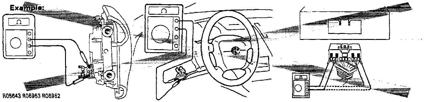
9. Use a volt/ohmmeter with high impedance (10 kohm / V minimum) for troubleshooting of the electrical circuit.
10. Information labels are attached to the periphery of the SRS components. Follow the instructions on the notices.
11. After work on the supplemental restraint system is completed, perform the SRS warning light check.
Spiral Cable (in Combination Switch):
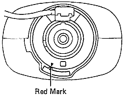
The steering wheel must be fitted correctly to the steering column with the spiral cable at the neutral position, otherwise cable disconnection and other troubles may result.
Steering Wheel Pad (with Airbag):
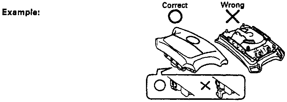
1. When removing the steering wheel pad or handling a new steering wheel pad, it should be placed with the pad top surface facing up.
In this case. the twin-lock type connector lock lever should be in the locked state and care should be taken to place it so the connector will not be damaged. In addition do not store a steering wheel pad on top of another one. Storing the pad with its metallic surface up may lead to a serious accident if the airbag inflates for some reason.
2. Never measure the resistance of the airbag squib. (This may cause the airbag to deploy, which is very dangerous.)
3. Grease should not be applied to the steering wheel pad and the pad should not be cleaned with detergents of any kind.
4. Store the steering wheel pad where the ambient temperature remains below 93°C (200°F), without high humidity and away from electrical noise.
5. When using electric welding, first disconnect the airbag connector (yellow color and 2 pins) under the steering column near the combination switch connector before starting work.
6. When disposing of a vehicle or the steering wheel pad alone, the airbag should be deployed using an SST before disposal. Carry out the operation in a safe place away from electrical noise.
Airbag Sensor Assembly:
1. Never reuse the center airbag sensor assembly involved in a collision when the SRS has deployed.
2. The connectors to the center airbag sensor assembly should be connected or disconnected with the sensor mounted on the floor. If the connectors are connected or disconnected while the center airbag sensor assembly is not mounted to the floor, it could cause undesired ignition of the supplemental restraint system.
3. Work must be started after 90 seconds from the time the ignition switch is turned to the LOCK position and the negative (-) terminal cable is disconnected from the battery, even if only loosening the set bolts of the center airbag sensor assembly.
Wire Harness and Connector:
The SRS wire harness is integrated with the cowl wire harness assembly and floor wire harness assembly. The wires for the SRS wire harness are encased in a yellow corrugated tube. All the connectors for the system are also a standard yellow color. If the SRS wire harness becomes disconnected or the connector becomes broken due to an accident, etc., repair or replace it.