Vehicle Speed Sensor: Description and Operation
Vehicle Speed Sensor Circuit Description
Vehicle Speed Sensor NO.1

This sensor is mounted in the combination meter. It contains a magnet which is rotated by the speed meter cable.
Turning the reed switch ON and OFF 4 times for every revolution of the speedmeter. It is then trtansmitted to the ECM. The ECM determines the vehicle speed based on thr frequency ot these pulse signals.
Vehicle Speed Sensor NO.2
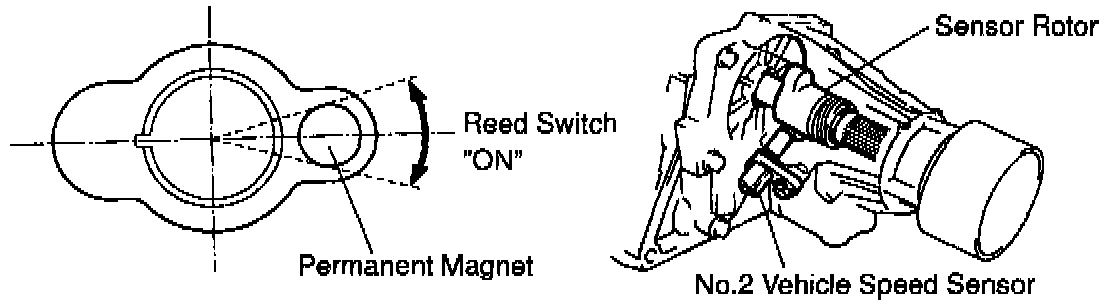
A rotor with built in permanent magnet is mounted on the output shaft. Every time the output shaft (and thus the rotor) makes one complete revolution, the permanent magnet activates the reed switch, which is built into the No.2 vehicle speed sensor, causing it to generate signal. This signal, which corresponds to the governor pressure in a conventional automatic transmission, is sent to the ECM, which uses it in controlling the shift points and operation of the lock-up clutch.
This sensor outputs one pulse for every one revolution of the output shaft.
If the No.2 vehicle speed sensor malfunctions, the ECM uses input singals from the No.1 vehicle speed sensor as a back-up signal.