Disassembly
DISASSEMBLY1. Install engine to engine stand for disassembly.
2. Remove Power Steering (PS) pump bracket.
Remove the 3 bolts and PS pump bracket.
3. Remove timing belt and pulleys.
4. Remove cylinder head.
5. Remove oil pan and oil pump.
6. Remove oil cooler.
7. Remove knock sensor.

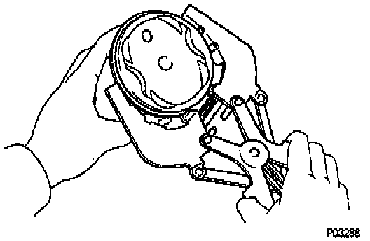
8. Remove generator drive belt adjusting bar, water pump and water pump cover assembly.
a. Remove the bolt and adjusting bar.
b. Remove the 3 bolts in the sequence shown, remove the water pump, water pump cover assembly and O-ring.

9. Remove rear oil seal retainer.
Remove the 6 bolts, retainer and gasket.
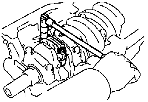
10. Check connecting rod thrust clearance.

Using a dial indicator, measure the thrust clearance while moving the connecting rod back and forth.
Standard thrust clearance: 0.160 - 0.312 mm (0.0063 - 0.0123 inch)
Maximum thrust clearance: 0.35 mm (0.0138 inch)
If the thrust clearance is greater than maximum, replace the connecting rod assembly. If necessary, replace the crankshaft.
11. Remove connecting rod caps and check oil clearance.
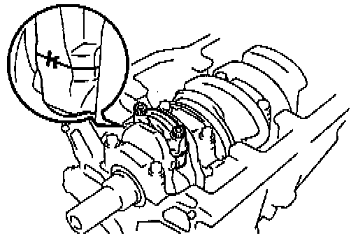
a. Check the matchmarks on the connecting rod and cap to ensure correct reassembly.
b. Remove the 2 connecting rod cap nuts.
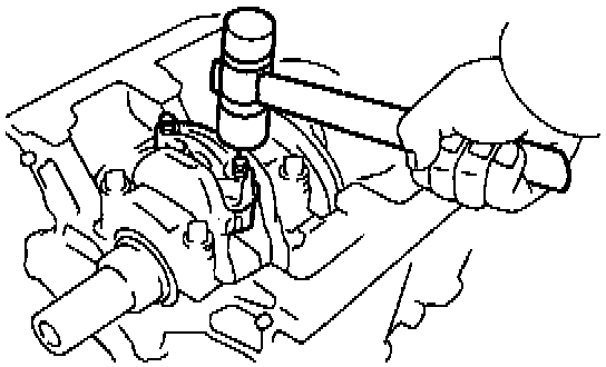
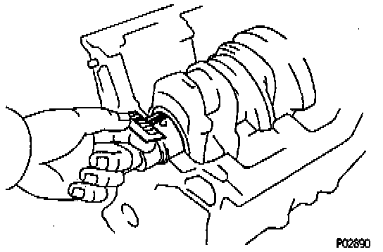
c. Using a plastic-faced hammer, lightly tap the connecting rod bolts and lift off the connecting rod cap.
HINT: Keep the lower bearing inserted with the connecting rod cap.

d. Cover the connecting rod bolts with a short piece of hose to protect the crankshaft from damage.
e. Clean the crank pin and bearing.
f. Check the crank pin and bearing for pitting and scratches.
If the crank pin or bearing is damaged, replace the bearings. If necessary, grind or replace the crankshaft.

g. Lay a strip of Plastigage across the crank pin.

h. Install the connecting rod cap.
NOTICE: Do not turn the crankshaft.
i. Remove the connecting rod cap.

j. Measure the Plastigage at its widest point.
Standard oil clearance:
STD: 0.024 - 0.055 mm (0.0009 - 0.0022 inch)
U/S 0.25: 0.023 - 0.069 mm (0.0009 - 0.0027 inch)
Maximum oil clearance: 0.08 mm (0.0031 inch)
If the oil clearance is greater than maximum, replace the bearings. If necessary, grind or replace the crankshaft.
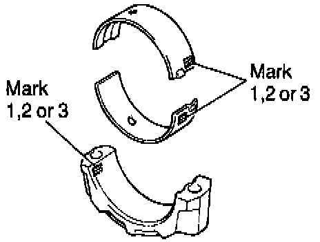
HINT: If using a standard bearing, replace it with one having the same number marked on the connecting rod cap. There are 3 sizes of standard bearings, marked "1", "2" and "3" accordingly.
Reference
Standard sized bearing center wall thickness:
Mark "1": 1.484 - 1.488 mm (0.0584 - 0.0586 inch)
Mark "2": 1.488 - 1.492 mm (0.0586 - 0.0587 inch)
Mark "3": 1.492 - 1.496 mm (0.0587 - 0.0589 inch)
k. Completely remove the Plastigage.
12. Remove piston and connecting rod assemblies.
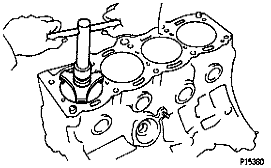
a. Using a ridge reamer, remove all the carbon from the top of the cylinder.
b. Cover the connecting rod bolts with a short piece of hose to protect the crankshaft from damage.
c. Push the piston, connecting rod assembly and upper bearing through the top of the cylinder block.
HINT:
- Keep the bearings, connecting rod and cap together.
- Arrange the piston and connecting rod assemblies in the correct order.
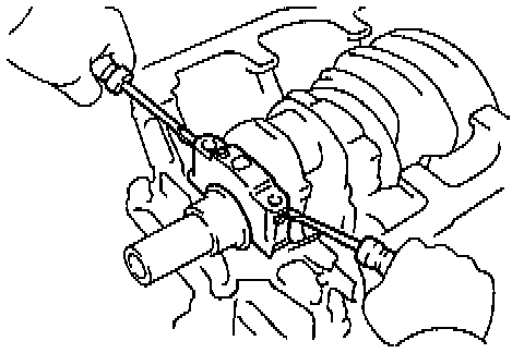
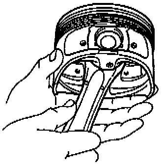
13. Check crankshaft thrust clearance.
Using a dial indicator, measure the thrust clearance while prying the crankshaft back and forth with a screwdriver.
Standard thrust clearance: 0.020 - 0.220 mm (0.0008 - 0.0087 inch)
Maximum thrust clearance: 0.30 mm (0.0118 inch)
If the thrust clearance is greater than maximum, replace the thrust washer as a set.
Thrust washer thickness: 2.440 - 2.490 mm (0.0961 - 0.0980 inch)
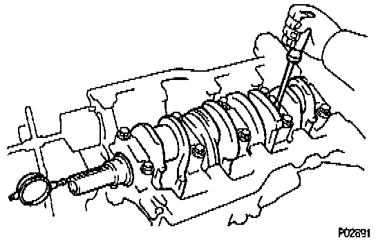
14. Remove main bearing caps and check oil clearance.
Main Bearing Cap Bolt Removal:

a. Uniformly loosen and remove the 10 main bearing cap bolts in several passes, in the sequence shown.
b. Using 2 screwdrivers, pry out the main bearing cap, and remove the 5 main bearing caps, 5 lower bearings and 2 lower thrust washers (No.3 main bearing cap only).
HINT:
- Keep the lower bearing and main bearing cap together.
- Arrange the main bearing caps and lower thrust washers in the correct order.
c. Lift out the crankshaft.
HINT: Keep the upper bearing and upper thrust washers together with the cylinder block.
d. Clean each main journal and bearing.
e. Check each main journal and bearing for pitting and scratches.
If the journal or bearing is damaged, replace the bearings. If necessary, grind or replace the crankshaft.
f. Place the crankshaft on the cylinder block.
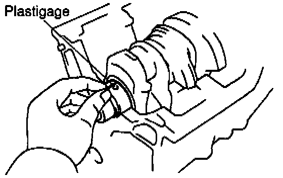
g. Lay a strip of Plastigage across each journal.

h. Install the main bearing caps.
NOTICE: Do not turn the crankshaft.
i. Remove the main bearing caps.
(See procedure (a) and (b) above)
j. Measure the Plastigage at its widest point.
Standard clearance:
No.3
STD: 0.025 - 0.044 mm (0.0010 - 0.0017 inch)
U/S 0.25: 0.027 - 0.067 mm (0.0011 - 0.0026 inch)
Others
STD: 0.015 - 0.034 mm (0.0006 - 0.0013 inch)
U/S 0.25: 0.019 - 0.059 mm (0.0007 - 0.0023 inch)
Maximum clearance: 0.08 mm (0.0031 inch)
HINT: If replacing the cylinder block subassembly, the bearing standard clearance will be:
No.3: 0.027 - 0.054 mm (0.001 - 0.0021 inch)
Others: 0.017 - 0.044 mm (0.0007 - 0.0017 inch)
If the oil clearance is greater than maximum, replace the bearings. If necessary, grind or replace the crankshaft.

HINT: If using a standard bearing, replace it with one having the same number. If the number of the bearing cannot be determined, select the correct bearing by adding together the numbers imprinted on the cylinder block and crankshaft, then selecting the bearing with the same number as the total. There are 5 sizes of standard bearings, marked "1", "2", "3", "4" and "5" accordingly.

EXAMPLE: Cylinder block "2" + Crankshaft "1" = Total number 3 (Use bearing "3")
Reference
Cylinder block main journal bore diameter:

Crankshaft main journal diameter:

Standard sized bearing center wall thickness:
No.3
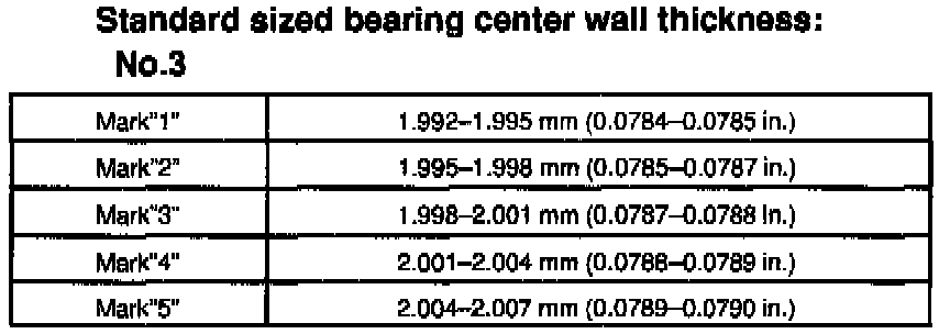
Others

k. Completely remove the Plastigage.
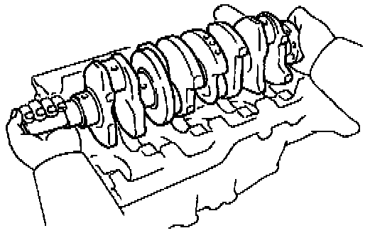
15. Remove crankshaft.
a. Lift out the crankshaft.
b. Remove the 5 upper bearings and 2 upper thrust washers from the cylinder block.
HINT: Arrange the main bearing caps, bearings and thrust washers in the correct order.
16. Check fit between piston and piston pin.
Try to move the piston back and forth on the piston pin.
If any movement is felt, replace the piston and pin as a set.
17. Remove piston rings.
a. Using a piston ring expander, remove the No.1 and No.2 piston rings.
b. Remove the 2 side rails and oil ring expander by hand.
HINT: Arrange the piston rings in correct order only.
18. Disconnect connecting rod from piston.

a. Using a small screwdriver, pry out the 2 snap rings.

b. Gradually heat the piston to 80 - 90°C (176 - 194°F).

c. Using a plastic-faced hammer and brass bar, lightly tap out the piston pin and remove the connecting rod.
HINT:
- The piston and pin are a matched set.
- Arrange the pistons, pins, rings, connecting rods and bearings in the correct order.