Inspection
INSPECTION1. Clean cylinder block.

a. Remove gasket material
Using a gasket scraper, remove all the gasket material from the top surface of the cylinder block.
b. Clean cylinder block
Using a soft brush and solvent, thoroughly clean the cylinder block.
2. Inspect top surface of cylinder block for flatness.

Using a precision straight edge and feeler gauge, measure the surfaces contacting the cylinder head gasket for warpage.
Maximum warpage: 0.05 mm (0.0020 inch)
If warpage is greater than maximum, replace the cylinder block.

3. Inspect cylinder for vertical scratches.
Visually check the cylinder for vertical scratches.
If deep scratches are present, rebore all the 4 cylinders. If necessary, replace the cylinder block.
4. Inspect cylinder bore diameter.

HINT: There are 3 sizes of the standard cylinder bore diameter, marked "1", "2" and "3" accordingly. The mark is stamped on the top of the cylinder block.

Using a cylinder gauge, measure the cylinder bore diameter at positions A, B and C in the thrust and axial directions.
Standard diameter:
Mark "1": 87.000 - 87.010 mm (3.4252 - 3.4256 inch)
Mark "2": 87.010 - 87.020 mm (3.4256 - 3.4262 inch)
Mark "3": 87.020 - 87.030 mm (3.4260 - 3.4264 inch)
Maximum diameter:
STD: 87.23 mm (3.4342 inch)
O/S 0.50: 87.73 mm (3.4350 inch)
If the diameter is greater than maximum, rebore all the 4 cylinders. If necessary, replace the cylinder block.
5. Remove cylinder ridge.

If the wear is less than 0.2 mm (0.008 inch), using a ridge reamer, grind the top of the cylinder.
6. Clean piston.

a. Using a gasket scraper, remove the carbon from the piston top.

b. Using a groove cleaning tool or broken ring, clean the piston ring grooves.

c. Using solvent and a brush, thoroughly clean the piston.
NOTICE: Do not use a wire brush.
7. Inspect piston oil clearance.

HINT: There are 3 sizes of the standard piston diameter, marked "1", "2" and "3" accordingly. The mark is stamped on the piston top.

a. Using a micrometer, measure the piston diameter at right angles to the piston pin center line, 23.5 mm (0.925 inch) from the piston head.
Piston diameter:
STD
Mark "1": 86.850 - 86.860 mm (3.4193 - 4.4197 inch)
Mark "2": 86.860 - 86.870 mm (3.4197 - 3.4201 inch)
Mark "3": 86.870 - 86.880 mm (3.4201 - 3.4205 inch)
O/S 0.50: 87.350 - 87.380 mm (3.4390 - 3.4402 inch)
b. Measure the cylinder bore diameter in the thrust directions. (See step 4 )
c. Subtract the piston diameter measurement from the cylinder bore diameter measurement.
Standard oil clearance: 0.14 - 0.16 mm (0.0055 - 0.0063 inch)
Maximum oil clearance: 0.18 mm (0.0071 inch)
If the oil clearance is greater than maximum, replace all the 4 pistons and rebore all the 4 cylinders. If necessary, replace the cylinder block.

HINT:
Use new cylinder block: Use a piston with the same number mark as the cylinder bore diameter marked on the cylinder block.

8. Inspect piston ring groove clearance.
Using a feeler gauge, measure the clearance between new piston ring and the wall of the ring groove.
Ring groove clearance:
No.1: 0.040 - 0.080 mm (0.0016 - 0.0031 inch)
No.2: 0.030 - 0.070 mm (0.0012 - 0.0028 inch)
If the clearance is greater than maximum, replace the piston.
9. Inspect piston ring end gap.
a. Insert the piston ring into the cylinder bore.
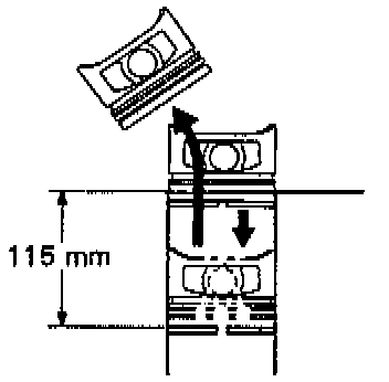
b. Using a piston, push the piston ring a little beyond the bottom of the ring travel, 115 mm (4.53 inch) from the top of the cylinder block.

c. Using a feeler gauge, measure the end gap.
Standard end gap:
No.1: 0.270 - 0.500 mm (0.0106 - 0.0197 inch)
No.2: 0.350 - 0.600 mm (0.0138 - 0.0236 inch)
Oil (Side rail): 0.200 - 0.550 mm (0.0079 - 0.0217 inch)
Maximum end gap:
No.1: 1.10 mm (0.0433 inch)
No.2: 1.20 mm (0.0472 inch)
Oil (Side rail): 1.15 mm (0.0453 inch)
If the end gap is greater than maximum, replace the piston ring.
If the end gap is greater than maximum, even with a new piston ring, rebore all the 4 cylinders or replace the cylinder block.
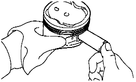
10. Inspect piston pin fit.
At 60°C (140°F), you should be able to push the piston pin into the piston pin hole with your thumb.
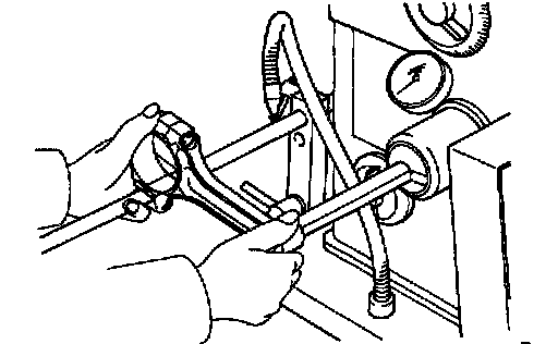
11. Inspect connecting rod.
Using a rod aligner and feeler gauge, check the connecting rod alignment.

- Check for bend.
Maximum bend: 0.05 mm (0.0020 inch) per 100 mm (3.94 inch)
If bend is greater than maximum, replace the connecting rod assembly.

- Check for twist.
Maximum twist: 0.15 mm (0.0059 inch) per 100 mm (3.94 inch)
If twist is greater than maximum, replace the connecting rod assembly.
12. Inspect piston pin oil clearance.

a. Using a caliper gauge, measure the inside diameter of the connecting rod bushing.
Bushing inside diameter: 22.005 - 22.017 mm (0.8663 - 0.8668 inch)

b. Using a micrometer, measure the piston pin diameter.
Piston pin diameter: 21.997 - 22.009 mm (0.8660 - 0.8665 inch)
c. Subtract the piston pin diameter measurement from the bushing inside diameter measurement.
Standard oil clearance: 0.005 - 0.011 mm (0.0002 - 0.0004 inch)
Maximum oil clearance: 0.05 mm (0.0020 inch)
If the oil clearance is greater than maximum, replace the bushing. If necessary, replace the piston and piston pin as a set.
13. Inspect connecting rod bolts.

a. Install the cap nut to the connecting rod bolt. Check that the cap nut can be turned easily by hand to the end of the thread.

b. If the cap nut cannot be turned easily, measure the outside diameter of the connecting rod bolt with a vernier caliper.
Standard diameter: 7.860 - 8.000 mm (0.3094 - 0.3150 inch)
Minimum diameter: 7.60 mm (0.2992 inch)
HINT: If the location of this area cannot be judged by visual inspection, measure the outer diameter at the location shown in the illustration.
If the outside diameter is less than minimum, replace the connecting rod bolt and nut as a set.
14. Inspect crankshaft for circle runout.
a. Place the crankshaft on V-blocks.

b. Using a dial indicator, measure the circle runout at the center journal.
Maximum circle runout: 0.06 mm (0.0024 inch)
If the circle runout is greater than maximum, replace the crankshaft.
15. Inspect main journals and crank pins.

a. Using a micrometer, measure the diameter of each main journal and crank pin.
Main journal diameter:
STD: 54.988 - 55.003 mm (2.1653 - 2.1655 inch)
U/S 0.25: 54.745 - 54.755 mm (2.1553 - 2.1557 inch)
Crank pin diameter:
STD: 51.985 - 52.000 mm (2.0466 - 2.0472 inch)
U/S 0.25: 51.745 - 51.755 (2.0372 - 2.0376 inch)
If the diameter is not as specified, check the oil clearance. If necessary, grind or replace the crankshaft.
b. Check each main journal and crank pin for taper and out-of-round as shown.
Maximum taper and out-of-round: 0.02 mm (0.0008 inch)
If the taper and out-of-round is greater than maximum, replace the crankshaft.
16. If necessary, grind and hone main journals and/or crank pins.
Grind and hone the main journals and/or crank pins to the finished undersized diameter. Install new main journal and/or crankshaft pin undersized bearings.
Oversized (O/S) Pistons for Cylinder Boring
HINT:
- Bore all the 4 cylinders for the oversized piston outside diameter.
- Replace all the piston rings with ones to match the oversized pistons.
17. Keep oversized pistons.
Oversized piston diameter:
O/S 0.50: 87.350 - 87.380 mm (3.4390 - 3.4402 inch)
18. Calculate amount to bore cylinders.
a. Using a micrometer, measure the piston diameter at right angles to the piston pin center line, 23.5 mm (0.925 inch) from the piston head.
b. Calculate the amount of each cylinder is to be rebored as follows:
Size to be rebored = P + C - H
P = Piston diameter
C = Piston oil clearance
0.140 - 0.160 mm (0.0055 - 0.0063 inch)
H = Allowance for honing
0.20 mm (0.0008 inch) or less
19. Bore and hone cylinder to calculated dimensions.
Maximum honing: 0.02 mm (0.0008 inch)
NOTICE: Excess honing will destroy the finished roundness.
REPLACEMENT
1. Replace connecting rod bushing.

a. Using Special Service Tool (SST) 09222 - 30010 or equivalent, and a press, Press out the bushing.

b. Align the oil holes of a new bushing and the connecting rod.
c. Using SST and a press, press in the busing.
d. Using a pin hole grinder, hone the bushing to obtain the standard specified clearance between the bushing and piston pin.

e. Check the piston pin fit at normal room temperature. Coat the piston pin with engine oil, and push it into the connecting rod with your thumb.

HINT: There are 2 methods (A and B) to replace the oil seed which are as follows:
2. Replace crankshaft front oil seal.
If oil pump is removed from cylinder block:
a. Using a screwdriver and hammer, tap out the oil seal.

b. Using SST 09226 - 10010 and a hammer, tap in a new oil seal until its sur face is flush with the oil pump body edge.
c. Apply Multipurpose (MP) grease to the oil seal lip.

If oil pump is installed to the cylinder block:
a. Using a knife, cut off the oil seal lip.
b. Using a screwdriver, pry out the oil seal.
NOTICE: Be careful not to damage the crankshaft. Tape the screw driver tip.

c. Apply MP grease to a new oil seal lip.
d. Using SST and a hammer, tap in the oil seal until its surface is flush with the oil pump body edge.
3. Replace crankshaft rear oil seal.
If rear oil seal retainer is removed from cylinder block:

a. Using a screwdriver and hammer, tap out the oil seal.

b. Using SST 09223 - 15030, 09950 - 70010 (099512 - 07100) and a hammer, tap in a new oil seal until its surface is flush with the rear oil seal retainer edge.
c. Apply MP grease to the oil seal lip.
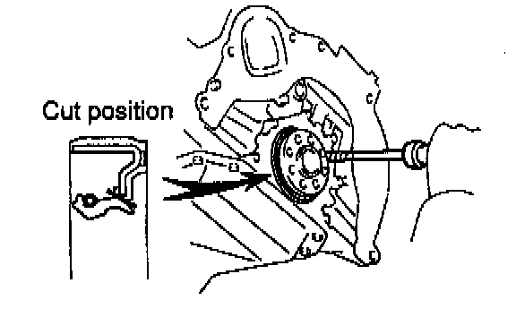
If rear oil seal retainer is installed to cylinder block:
a. Using a knife, cut off the oil seal lip.
b. Using a screwdriver, pry out the oil seal.
NOTICE: be careful not to damage the crankshaft. Tape the screw driver tip.

c. Apply MP grease to a new oil seal lip.
d. Using SST and a hammer, tap in the oil seal until its surface is flush with the rear oil seal retainer edge.