Cylinder Head Installation
INSTALLATION
1. Place cylinder head on cylinder block.
a. Place a new cylinder head gasket on the cylinder block.
NOTICE: Be careful of the installation direction.
b. Place the cylinder head on the cylinder head gasket.
Cylinder Head Installation:

2. Install cylinder head boots.
HINT:
- The cylinder head bolts are tightened in 2 progressive steps (steps (b) and (d)).
- If any cylinder head bolt is broken or deformed, replace it.
a. Apply a light coat of engine oil on the threads and under the heads of the cylinder head bolts.
b. Install and uniformly tighten the 10 cylinder head bolts and plate washers in several passes, in the sequence shown.
Torque: 49 Nm (36 ft. lbs.)
If any one of the cylinder head bolts does not meet the torque specification, replace the cylinder head bolt.
c. Mark the front of the cylinder head bolt head with paint.

d. Retighten the cylinder head bolts 90° in the numerical order shown.
e. Check that the painted mark is now at a 90° angle to the front.

3. Install spark plug tubes.
a. Clean the cylinder head tube holes of any residual adhesive, oil or foreign particles. Remove any oil with kerosene or gasoline.
b. Screw the threads of the spark plug tube coated with adhesive into the cylinder head.
c. Using the spark plug tube nut and a 30 mm socket wrench, tighten the spark plug tubes.
Torque: 39 Nm (29 ft. lbs.)
4. Assemble exhaust camshaft.
a. Mount the camshaft in a vise.
NOTICE: Be careful not to damage the camshaft.

b. Install these parts:
1) Camshaft gear spring
2) Camshaft sub-gear
3) Wave washer
HINT: Align the pins on the gears with the spring ends.

c. Using snap ring pliers, install the snap ring.

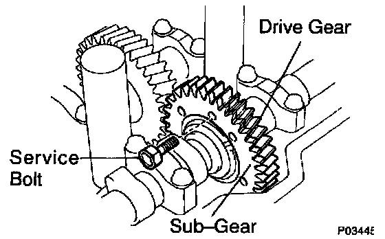
d. Using Special Service Tool (SST) 09960 - 10010 (09962 - 01000, 09963 - 00500) or equivalent, align the holes of the camshaft drive gear and sub-gear by turning camshaft sub-gear clockwise, and install a service bolt.
e. Align the gear teeth of the drive gear and sub-gear, and tighten the service bolt.
5. Install camshaft
NOTICE: Since the thrust clearance of the camshaft is small, the camshaft must be kept level while it is being installed. If the camshaft is not kept level, the portion of the cylinder head receiving the shaft thrust may crack or be damaged, causing the camshaft to seize or break. To avoid this, the following steps should be carried out.
a. Intake camshaft:
1) Apply Multipurpose (MP) grease to the thrust portion of the camshaft.

2) Place the intake camshaft at 80 - 115° Before Top Dead Center (BTDC) of camshaft angle on the cylinder head.
HINT: The above angle arrows the No.1 and No.3 cylinder cam lobes of the intake camshaft to push their valve lifters evenly.

3) Apply seal packing to the No.1 bearing cap as shown.
Seal packing: Part No. 08826 - 00080 or equivalent

4) Install the bearing caps in their proper locations.
Intake Camshaft Installation:

5) Apply a light coat of engine oil on the threads and under the heads of the bearing cap bolts.
6) Install and uniformly tighten the 10 bearing cap bolts in several passes, in the sequence shown.
Torque: 19 Nm (14 ft. lbs.)

7) Apply MP grease to a new oil seal lip.
8) Using SST 09223 - 46011 and a hammer, tap in the oil seal.

b. Exhaust camshaft:
1) Set the knock pin of the intake camshaft at 10 - 45° BTDC of camshaft angle.
HINT: The above angle allows the No.2 and No.4 cylinder cam lobes of the exhaust camshaft to push their valve lifters evenly.
2) Apply MP grease to the thrust portion of the camshaft.
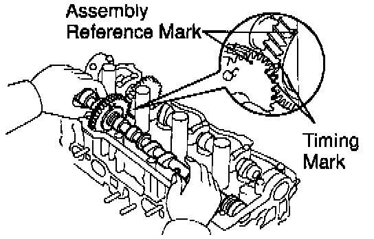
3) Engage the exhaust camshaft gear to the intake camshaft gear by matching the timing marks on each gear.
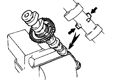
4) Roll down the exhaust camshaft onto the bearing journals while engaging gears with each other.
NOTICE: There are also assembly reference marks on each gear as shown in the illustration. Do not use these marks.
5) Turn the intake camshaft clockwise or counterclockwise a little until the exhaust camshaft sits in the bearing journals evenly without rocking the camshaft on the bearing journals.
NOTICE: It is very important to replace the camshaft in the bearing journals evenly while tightening bearing caps in the subsequent steps.

6) Install the bearing caps in their proper locations.
Exhaust Camshaft Installation:

7) Apply a light coat of engine oil on the threads and under the heads of the bearing cap bolts.
8) Install and uniformly tighten the 10 bearing cap bolts in several passes, in the sequence shown.
Torque: 19 Nm (14 ft. lbs.)
9) Remove the service bolt.
6. Check and adjust valve clearance.
Turn the camshaft and position the cam lobe upward, and check and adjust the valve clearance.

7. Install semi-circular plugs.
a. Remove any old packing Formed In Place Gasket (FIPG) material.
b. Apply seal packing to the semi-circular plug grooves.
Seal packing: Part No. 08826 - 00080 or equivalent

c. Install the 2 semi-circular plugs to the cylinder head.
8. Install Positive Crankcase Ventilation (PCV) valve, PCV hose and high-tension cord clamp to cylinder head.
a. Install the high-tension cord clamp with the bolt.
b. Install the grommet, the PCV valve and hose assembly.
c. Install the PCV hose.
9. Install cylinder head cover.
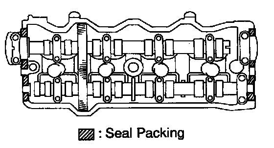
a. Remove any old packing (FIPG) material.
b. Apply seal packing to the cylinder head as shown in the illustration.
Seal packing: Part No. 08826 - 00080 or equivalent

c. Install the gasket to the head cover.
d. Install the head cover with the 4 grommets and nuts. Uniformly tighten the nuts in several passes.
Torque: 44 Nm (33 ft. lbs.)
HINT: Install the grommets so that their markings are as shown in the illustration.
10. Install oil pressure switch.

a. Apply adhesive to 2 or 3 threads.
Adhesive: Part No. 08833 - 00080, THREE BOND 1324 or equivalent
b. Install the oil pressure switch.

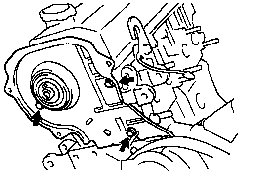
11. Install engine hangers and generator bracket.
a. Install the generator bracket and RH engine hanger assembly with the 3 bolts.
Torque: 25 Nm (18 ft. lbs.)
b. Install the LH engine hanger with the bolt.
Torque: 25 Nm (18 ft. lbs.)
12. Install NO.3 timing belt cover.
Install the timing belt cover with the 3 bolts.
Torque: 7.8 Nm (69 inch lbs.)
13. Temporarily install NO.1 idler pulley and tension spring.
14. Install camshaft timing pulley.
15. Connect timing belt to camshaft timing pulley.

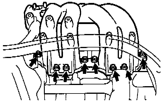
16. Install injectors and delivery pipe.
a. California: Install a new insulator and grommet to each injector.
b. Except California: Install a new grommet to each injector.
c. California: Apply a light coat of gasoline onto 2 new O-rings, and install them to each injector.
d. Except California: Apply a light coat of gasoline onto a new O-ring, and install it to each injector.

e. While turning the injector clockwise and counterclockwise, push it to the delivery pipe. Install the 6 injectors.
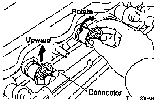
f. Position the injector connector upward.
g. Install these parts to the cylinder head:
1) 2 spacers
2) Except California: 4 new insulators
h. Attach the 4 injectors together with the delivery pipe to the cylinder head.
i. Temporarily install the 2 bolts holding the delivery pipe to the cylinder head.
j. Check that the injectors rotate smoothly.
HINT: If injectors do not rotate smoothly, the probable cause is incorrect installation of O-rings. Replace the O-rings.
k. Position the injector connector upward.
l. Tighten the 2 bolts holding the delivery pipe to the cylinder head.
Torque: 13 Nm (9 ft. lbs.)

17. California only: Install air hose for air assist system.
Connect the air hose to the cylinder head port.
18. Install intake manifold.
a. Insert the intake manifold between the cylinder head and dash panel.
b. Insert the engine wire between the cylinder head and in take manifold.
c. Install a new gasket and the intake manifold with the 6 bolts and 2 nuts. Uniformly tighten the bolts and nuts in several passes.
Torque: 19 Nm (14 ft. lbs.)
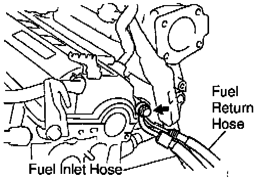
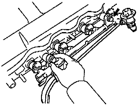
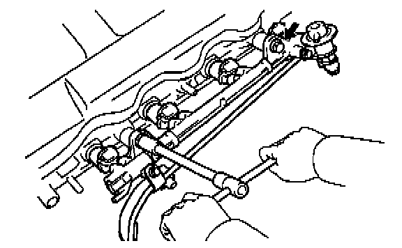
19. Connect fuel inlet hose to delivery pipe.
Connect the fuel inlet pipe to the delivery pipe with 2 new gaskets and the union bolt.
Torque: 34 Nm (25 ft. lbs.)
20. Connect fuel return hose to return hose.
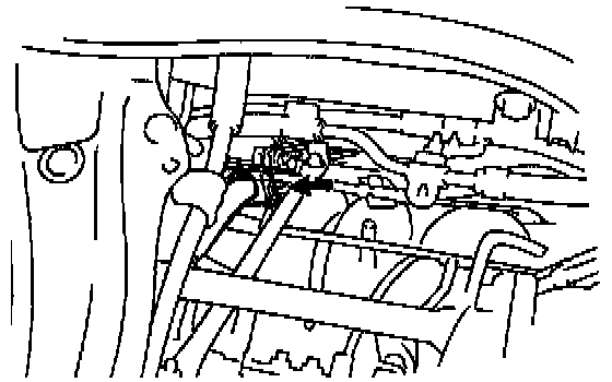
21. Install engine wire.
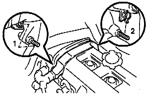
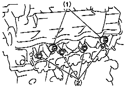
a. Install the engine wire protector to the 2 mounting bolts of the No.2 timing belt cover in the sequence shown.
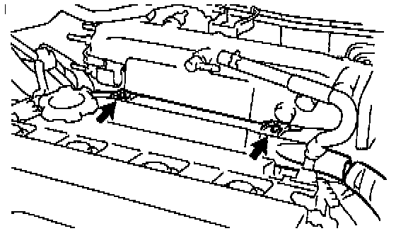
b. Install the the engine wire protector to the 2 brackets on the front side of the intake manifold.
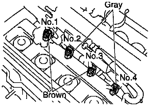
c. Connect the 4 injector connectors.
HINT: The No.1 and No.3 injector connectors are brown, and the No.2 and No.4 injector connectors are gray.
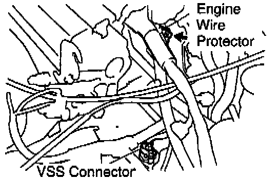
d. Install the the engine wire protector to the LH side of the intake manifold with the bolt.
e. Connect the VSS sensor connector.
f. Install the engine wire protector to the bracket on the starter.
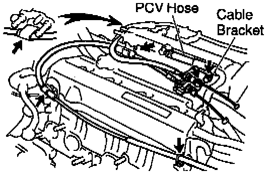
22. Install accelerator, A/T throttle control cables and bracket.
a. Install the cable bracket to the intake manifold with the 2 bolts.
b. Install the control cables to the 4 clamps.
23. Connect PCV hose to intake manifold.

24. Install Vacuum Switching Valve (VSV) for Exhaust Gas Recirculation (EGR).
a. Install the VSV with the bolt.
b. Connect the VSV connector.
25. Connect knock sensor 1 connector.
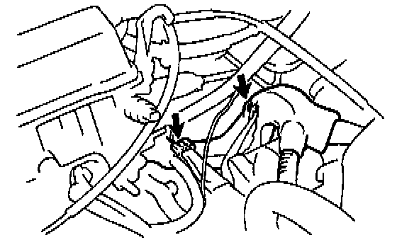
26. Install ground wires.
Install the 2 ground wires with the bolt.
27. Install air tube.

a. Install the air tube and hose bracket (for EGR) with the 2 bolts.

b. Connect these hoses:
1) 2 PS air hoses to air tube

2) Power Steering (PS) air hose to intake manifold
3) Vacuum sensing hose to fuel pressure regulator

28. Install A/T throttle control cable to intake manifold.
Install the control cable to the clamp on the rear side of the intake manifold.
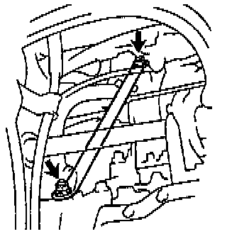
29. Install intake manifold stay.
Install the intake manifold stay with the bolt and nut.
Torque:
Bolt 21 Nm (15 ft. lbs.)
Nut 44 Nm (32 ft. lbs.)
30. Install EGR valve and vacuum modulator.

a. Install a new gasket and the EGR valve with the union nut and 2 nuts.
Torque:
Nut 13 Nm (9 ft. lbs.)
Union bolt 59 Nm (43 ft. lbs.)

b. Install the vacuum modulator to the clamp on the intake manifold.
c. Connect the 2 vacuum hoses to the VSV for the EGR.
d. Install the hose clamp to the bracket on the air tube.
e. Connect the Evaporative Emission (EVAP) hose to the charcoal canister.
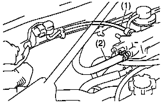
31. Install hoses.
Connect these hoses:
1) Manifold Absolute Pressure (MAP) sensor vacuum hose to gas filter on intake manifold
2) Brake booster vacuum hose to intake manifold
32. Install throttle body.

33. Install water bypass pipe.
a. Install a new gasket to the water pump cover.
b. Install a new O-ring to the bypass pipe.
c. Apply soapy water on the O-ring.
d. Connect the water bypass pipe to the water pump cover.
e. Install the bypass pipe with the 2 nuts and 2 bolts.
Torque:
Nut 9.3 Nm (82 inch lbs.)
Bolt 19 Nm (14 ft. lbs.)

f. Connect these hoses:
- Idle Air Control (IAC) valve water bypass hose to water bypass pipe.
- Heater water hose to water bypass pipe.
- 2 oil cooler water bypass hoses to oil cooler.
g. Install the oil cooler heat protector with the 2 nuts and bolt.
34. Install water outlet.
a. Install a new gasket and the water outlet with the 2 nuts.
Torque: 15 Nm (11 ft. lbs.)

b. Connect these hoses to the water outlet:
1) Radiator hose
2) Water bypass pipe hose
3) Heater water hose
4) Vacuum hose (from P port of throttle body) to upper port of Thermal Vacuum Valve (TVV) for EVAP
5) Vacuum hose (from charcoal canister) to lower port of TVV for EVAP
6) IAC valve water bypass hose
c. Connect these connectors:
- Engine Coolant Temperature (ECT) sensor connector
- ECT sender gauge connector
35. Connect oil pressure switch connector.
36. Assemble exhaust manifold and front Three-Way Catalytic Converter (TWC).
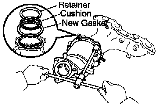
a. Place the cushion, retainer and a new gasket on the TWC.
b. Install the TWC to the exhaust manifold with the 3 bolts and 2 new nuts.
Torque: 29 Nm (22 ft. lbs.)
c. Install the lower manifold heat insulator with the 5 bolts.
d. Install the 2 TWC heat insulators with the 8 bolts.

37. Install oxygen sensor (Bank 1 Sensor 1) to exhaust manifold.
Install a new gasket and the oxygen sensor with 2 new nuts.
Torque: 20 Nm (14 ft. lbs.)
38. Install oxygen sensor (Bank 1 Sensor 2) to front TWC.
Torque: 44 Nm (33 ft. lbs.)
39. Install exhaust manifold and front two assembly.
a. Install a new gasket, the exhaust manifold and TWO assembly with the 6 nuts. Uniformly tighten the nuts in several passes.
Torque: 49 Nm (36 ft. lbs.)

b. Install the RH exhaust manifold stay with the 2 bolts and 2 nuts.
Torque: 42 Nm (31 ft. lbs.)
c. Install the upper manifold heat insulator with the 5 bolts.
d. Install the LH exhaust manifold stay with the bolt and nut.
Torque:
Bolt 39 Nm (29 ft. lbs.)
Nut 42 Nm (31 ft. lbs.)
e. Connect these connectors:
- Oxygen sensor (bank 1 sensor 1) connector
- Oxygen sensor (bank 1 sensor 2) connector
40. Install front exhaust pipe.
41. Install generator.
42. Install distributor.
43. Install air cleaner case and cap.
44. Fill with engine coolant.
45. Start engine and check for leaks.
46. Recheck engine coolant level and oil level.