Part 1
INSPECTION1. Clean top surfaces of pistons and cylinder block.

a. Turn the crankshaft, and bring each piston to Top Dead Center (TDC). Using a gasket scraper, remove all the carbon from the piston top surface.

b. Using a gasket scraper, remove all the gasket material from the cylinder block surface.
c. Using compressed air, blow carbon and oil from the bolt holes.
CAUTION: Protect your eyes when using high-pressure compressed air.
2. Inspect top surface of cylinder block for flatness.
3. Clean cylinder head.

a. Remove gasket material.
Using a gasket scraper, remove all the gasket material from the cylinder block contact surface.
NOTICE: Be careful not to scratch the cylinder block contact surface.

b. Clean combustion chambers.
Using a wire brush, remove all the carbon from the combustion chamber.
NOTICE: Be careful not to scratch the cylinder block contact surface.
c. Clean valve guide bushings.
Using a valve guide bushing brush and solvent, clean all the Guide bushings.
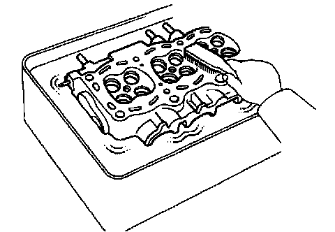
d. Clean cylinder head. Using a soft brush and solvent, thoroughly clean the cylinder head.
4. Inspect cylinder head.

a. Inspect for flatness.
Using a precision straight edge and feeler gauge, measure the surfaces contacting the cylinder block and the manifolds for warpage.
Maximum warpage:
Cylinder block side: 0.05 mm (0.0020 inch)
Manifold side: 0.08 mm (0.0031 inch)
If warpage is greater than maximum, replace the cylinder head.

b. Inspect for cracks.
Using a dye penetrant, check the combustion chamber, intake ports, exhaust ports and cylinder block surface for cracks.
If cracked, replace the cylinder head.

5. Clean valves.
a. Using a gasket scraper, chip off any carbon from the valve head.
b. Using a wire brush, thoroughly clean the valve.
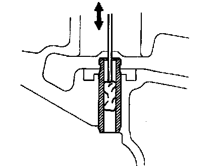
6. Inspect valve stems and guide bushings.

a. Using a caliper gauge, measure the inside diameter of the guide bushing.
Bushing inside diameter: 6.010 - 6.030 mm (0.2366 - 0.2374 inch)

b. Using a micrometer, measure the diameter of the valve stem.
Valve stem diameter:
Intake: 5.970 - 5.985 mm (0.2350 - 0.2356 inch)
Exhaust: 5.965 - 5.980 mm (0.2348 - 0.2354 inch)
c. Subtract the valve stem diameter measurement from the guide bushing inside diameter measurement.
Standard oil clearance:
Intake: 0.025 - 0.060 mm (0.0010 - 0.0024 inch)
Exhaust: 0.030 - 0.065 mm (0.0012 - 0.0026 inch)
Maximum oil clearance:
Intake: 0.08 mm (0.0031 inch)
Exhaust: 0.10 mm (0.0039 inch)
If the clearance is greater than maximum, replace the valve and guide bushing.

7. Inspect and grind valves.
a. Grind the valve enough to remove pits and carbon.
b. Check that the valve is ground to the correct valve face angle.
Valve face angle: 44.5°

c. Check the valve head margin thickness.
Standard margin thickness: 0.8 - 1.2 mm (0.031 - 0.047 inch)
Minimum margin thickness: 0.5 mm (0.020 inch)
If the margin thickness is less than minimum, replace the valve.
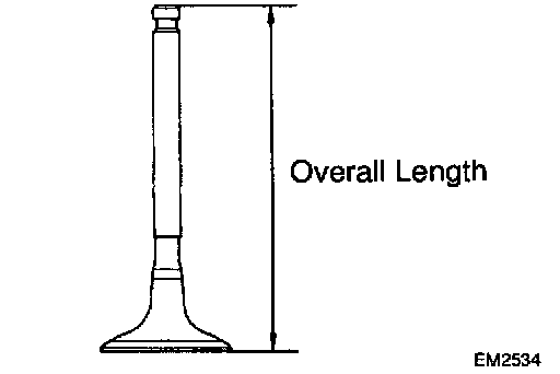
d. Check the valve overall length.
Standard overall length:
Intake: 97.40 - 97.80 mm (3.8346 - 3.8504 inch)
Exhaust: 98.25 - 98.65 mm (3.8681 - 3.8839 inch)
Minimum overall length:
Intake: 97.1 mm (3.823 inch)
Exhaust: 98.0 mm (3.858 inch)
If the overall length is less than minimum, replace the valve.

e. Check the surface of the valve stem tip for wear.
If the valve stem tip is worn, resurface the tip with a grinder or replace the valve.
NOTICE: Do not grind off more than the minimum length.
8. Inspect and clean valve seats.

a. Using a 45° carbide cutter, resurface the valve seats.
Remove only enough metal to clean the seats.

b. Check the valve seating position.
Apply a light coat of prussian blue (or white lead) to the valve face. Lightly press the valve against the seat. Do not rotate valve.
c. Check the valve face and seat for the following:
- If blue appears 360° around the face, the valve is concentric. If not, replace the valve.
- If blue appears 360° around the valve seat, the guide and face are concentric. If not, resurface the seat.
- Check that the seat contact is in the middle of the valve face with the following width:
1.0 - 1.4 mm (0.039 - 0.055 inch)

If not, correct the valve seats as follows:
1) If the seating is too high on the valve face, use 30° and 45° cutters to correct the seat.

2) If the seating is too low on the valve face, use 75° and 45° cutters to correct the seat.

d. Hand-lap the valve and valve seat with an abrasive compound.
e. After hand-lapping, clean the valve and valve seat.
9. Inspect valve springs.

a. Using a steel square, measure the deviation of the valve spring.
Maximum deviation: 2.0 mm (0.079 inch)
If the deviation is greater than maximum, replace the valve spring.

b. Using a vernier caliper, measure the free length of the valve spring.
Free length: 40.95 - 42.80 mm (1.6122 - 1.6850 inch)
If the free length is not as specified, replace the valve spring.

c. Using a spring tester, measure the tension of the valve spring at the specified installed length.
Installed tension: 164 - 189 N (36.8 - 42.5 lbs.) at 34.7 mm (1.366 inch)
If the installed tension is not as specified, replace the valve spring.

10. Inspect camshaft for runout.
a. Place the camshaft on V-blocks.
b. Using a dial indicator, measure the circle runout at the center journal.
Maximum circle runout: 0.04 mm (0.0016 inch)
If the circle runout is greater than maximum, replace the camshaft.
11. Inspect cam lobes.

Using a micrometer, measure the cam lobe height.
Standard cam lobe height:
Intake: 42.01 - 42.11 mm (1.6539 - 1.6579 inch)
Exhaust: 40.06 - 40.16 mm (1.5772 - 1.5811 inch)
Minimum cam lobe height:
Intake: 41.90 mm (1.6496 inch)
Exhaust: 39.95 mm (1.5728 inch)
If the cam lobe height is less than minimum, replace the camshaft.