Differential Assembly
DIFFERENTIAL ASSEMBLY
Components
Differential Case Disassembly
1. REMOVE RING GEAR

a. Loosen the staked part of the lock plate.
b. Remove the 8 bolts and locking plates.

c. Using a copper hammer, tap on the ring gear to remove it from the case.

2. REMOVE SIDE BEARINGS
Fasten Special Service Tools (SST) under the bearing above the cutouts on the speedometer drive gear. Remove the bearing from the case.
SST 09502-10012

3. CHECK SIDE GEAR BACKLASH
Using a dial gauge, measure the backlash of each side gear while holding one pinion toward the case.
Standard backlash: 0.05 - 0.20 mm (0.0020 - 0.0079 inch)
4. DISASSEMBLE DIFFERENTIAL CASE

a. Drive out the pinion shaft lock pin from the side on which the ring gear is installed.

b. Remove the pinion shaft from the case.
c. Remove the 2 pinions and 2 side gears with the 4 thrust washers.

5. REMOVE LH OIL SEAL
Using a hammer and screwdriver, remove the oil seal.

6. REMOVE BEARING OUTER RACE FROM LH SIDE BEARING RETAINER
Using SST, press out the outer race and shim.
SST 09350-32014 (09351-32090)

7. REMOVE RH OIL SEAL
Using a hammer and screwdriver, remove the oil seal.
Differential Case Assembly

1. INSTALL RH OIL SEAL
a. Using SST, drive in a new oil seal until its surface is flush with the surface of the case.
SST 09350-32014 (09351-32130, 09351-32150)
b. Coat the oil seal lip with MP grease.

2. INSTALL BEARING OUTER RACE TO LH SIDE BEARING RETAINER
a. Place the shim onto the retainer.
b. Using SST, press a new outer race into the retainer.
SST 09350-32014 (09351-32111, 09351-32130)
HINT: Use the 2.60 mm (0.1024 inch) thick shim.

3. INSTALL LH OIL SEAL
a. Using SST, drive in a new oil seal.
SST 09350-32014 (09351-32130, 09351-32150)
Oil seal drive in depth: 2.7 mm (0.106 inch)
b. Coat the oil seal lip with MP grease.
4. ASSEMBLE DIFFERENTIAL CASE

a. Install the removed thrust washers to the side gears.

b. Install the side gears with thrust washers, pinion thrust washers and pinion gears.

c. Install the pinion shaft.

d. Check the side gear backlash. Measure the side gear backlash while holding one pinion gear toward the case.
Standard backlash: 0.05 - 0.20 mm (0.0020 - 0.0079 inch)
Referring to the table as shown, select thrust washers which will ensure that the backlash is within specification. Try to select washers of the same size for both sides.

Thrust Washer Thickness
If the backlash is not within specification, install a thrust washer of a different thickness.

e. Using a hammer and punch, drive the lock pin through the case and hole in the pinion shaft.

f. Stake the differential case.
5. INSTALL SIDE BEARINGS

a. Install the speedometer drive gear onto the differential case.

b. Using SST and a press, press in the RH side bearing onto the differential case.
SST 09350-32014 (09351-32090, 09351-32120)

c. Using SST and a press, press in the LH side bearing onto the differential case.
SST 09710-28020 (09710-08040)
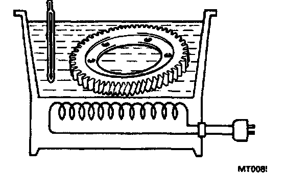
6. INSTALL RING GEAR
a. Clean the contact surface of the differential case.
b. Heat the ring gear to about 100°C (212°F) in an oil bath.
c. Carefully remove the ring gear from the water.
NOTICE: Do not heat the ring gear above 110°C (230°F).
d. Clean the contact surface of the ring gear with cleaning solvent.
e. Quickly install the ring gear on the differential case.

f. Install new locking plates and set bolts. When the ring gear has cooled sufficiently, tighten the set bolts uniformly a little at a time. Torque the bolts.
Torque: 97 Nm (985 kgf.cm, 71 ft. lbs.)

g. Using a hammer and drift punch, stake the locking plates.
HINT: Stake one claw flush with the flat surface of the nut. For the claw contacting the protruding portion of the nut, stake only the half on the tightening side.
Drive Pinion Disassembly

1. REMOVE DRIVE PINION SHAFT BEARING
Using SST, press out the bearing.
SST 09950-00020

2. REMOVE OIL SEALS FROM CAGE
Using SST, press out the two oil seals together.
SST 09350-32014 (09351-32090)

3. REMOVE SHAFT BEARING OUTER RACE FROM CAGE
Using a hammer and brass bar, drive out the outer race from the cage.

4. REMOVE COUNTER DRIVEN GEAR BEARING
Using SST, press out the bearing.
SST 09950-00020
Drive Pinion Shaft Assembly

1. INSTALL COUNTER DRIVEN GEAR BEARING
Using SST, press in a new bearing.
SST 09350-32014 (09351-32090)
2. INSTALL OIL SEALS TO CAGE

a. Using SST, press in a new oil seal with the lip facing downward.
SST 09350-32014 (09351-32090)
Oil seal press in depth (from flat end): 9.5 mm (0.374 inch)

b. Measure the oil seal press in depth.
Oil seal press in depth: 4 mm (0.16 inch)

c. With the oil seal lip facing upward, use SST to press in a new oil seal until its end is flush with the surface of the cage.
SST 09350-32014 (09351-32090)
d. Coat the oil seal lip with MP grease.

3. INSTALL SHAFT BEARING OUTER RACE TO CAGE
Using SST, press a new outer race into the cage.
SST 09350-32014 (09351-32111, 09351-32130)

4. INSTALL DRIVE PINION SHAFT BEARING
Using SST, press in the bearing.
SST 09350-32014 (09351-32100)

5. PLACE BEARING CAGE ONTO DRIVE PINION SHAFT
Be careful not to damage the oil seal with the splines.
Differential Side Bearing Preload Adjustment

1. PLACE OUTER RACE AND ADJUSTING SHIM ONTO RH SIDE BEARING
Use the adjusting shim which was removed or one 2.40 mm (0.0945 inch) thick.

2. PLACE DIFFERENTIAL CASE INTO TRANSAXLE CASE
Be sure to install the adjusting shim.

3. INSTALL LH BEARING RETAINER
a. Do not install the 0-ring yet.
b. Do not coat the bolt threads with sealant yet.
c. Temporarily tighten the bolts evenly and gradually while turning the ring gear.

4. INSTALL RH SIDE BEARING CAP
Tighten the bolts evenly and gradually while turning the ring gear.
Torque: 72 Nm (730 kgf.cm, 53 ft. lbs.)

5. TIGHTEN LH BEARING RETAINER
Torque: 19 Nm (195 kgf.cm, 14 ft. lbs.)


6. ADJUST SIDE BEARING PRELOAD
Using SST and a torque meter, measure the preload of the ring gear.
SST 09564-32011
Preload (at starting):
New bearing: 1.0 - 1.6 Nm (10 - 16 kgf.cm, 8.7 - 13.9 inch lbs.)
Reused bearing: 0.5 - 0.8 Nm (5 - 8 kgf.cm, 4.3 - 6.9 inch lbs.)

If the preload is not within specification, remove the differential case assembly. Reselect the RH adjusting shim.
HINT: The preload will change by about 0.3 - 0.4 Nm (3 - 4 kgf.cm, 2.6 - 3.5 inch lbs.) with a change in shim thickness of 0.05 mm (0.0020 inch).

7. REMOVE DIFFERENTIAL CASE AND COMPONENT PARTS
If the preload is adjusted within specification, remove the bearing retainer, differential case, RH side bearing and shim. Be careful not to lose the adjusting shim.