Part 1
OVERDRIVE UNIT
Components
Overdrive Brake Disassembly

1. REMOVE PISTON RETURN SPRING
a. While pushing the return spring, remove the snap ring with a screwdriver.
b. Remove the piston return spring.

2. REMOVE CUSHION PLATE, PLATES, DISCS AND FLANGE

3. REMOVE PISTON FROM DRUM
Apply compressed air to oil hole to remove the piston.
HINT: Blow with the gun slightly away from the oil hole, and be careful that the piston does not tilt.

4. REMOVE O-RINGS
Remove the inner and outer O-rings from the piston.
Overdrive Brake Inspection

INSPECT DISCS, PLATES AND FLANGE
Check if the sliding surfaces of the discs, plates and flange are worn or burnt. If necessary, replace them.
HINT:
- If the lining of the disc is peeling off or discolored, or even if a part of the printed numbers are defaced, replace all discs.
- Before assembling new discs, soak them in Automatic Transmission Fluid (ATF) for at least 15 minutes.
Overdrive Direct Clutch Disassembly

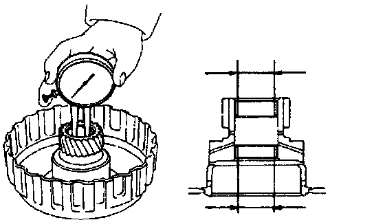
1. CHECK PISTON STROKE OF DIRECT CLUTCH
Using a dial indicator, measure the piston stroke while applying and releasing compressed air (392 - 785 kPa, 4 - 8 kgf/cm2, 57- 114 psi).
Piston stroke: 1.21 - 1.91 mm (0.0476 - 0.0752 inch)
If the piston stroke is greater than the maximum, inspect each component.

2. REMOVE OVERDRIVE DIRECT CLUTCH FROM CASE

3. REMOVE BEARING AND RACE FROM CLUTCH DRUM AND CASE

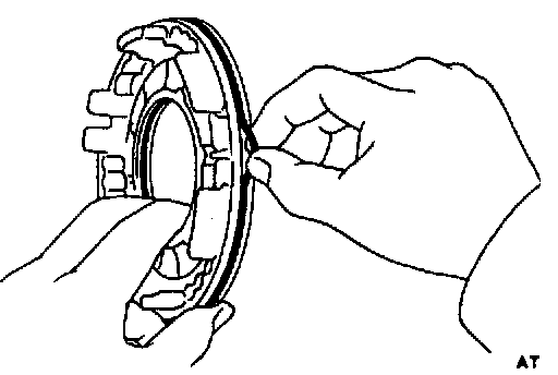
4. REMOVE SNAP RING WITH SCREWDRIVER

5. REMOVE FLANGES, DISCS AND PLATES

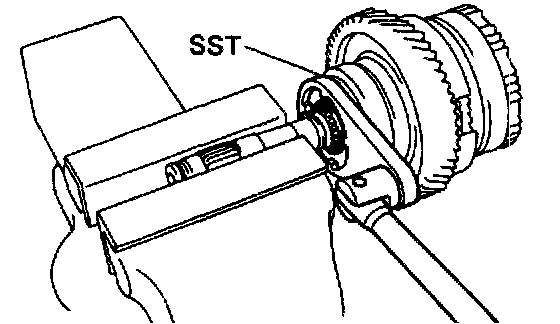
6. REMOVE PISTON RETURN SPRING
a. Place Special Service Tools (SST) on the spring retainer and compress the spring with a shop press.
SST 09350-32014 (09351-32070, 09351-32200)
b. Remove the snap ring.

c. Remove the piston return spring.

7. REMOVE PISTON FROM CLUTCH DRUM
a. Install the clutch drum of the case.
b. Apply compressed air to the pressure apply hole of the case.
c. Remove the piston from the clutch drum. If the piston does not come out completely, use needle-nose pliers to remove it.
d. Remove the clutch drum from the case.

8. REMOVE O-RINGS
Remove the 2 O-rings from the piston.
Overdrive Direct Clutch Inspection

1. INSPECT OVERDRIVE DIRECT CLUTCH
a. Check that the check ball is free by shaking the piston.
b. Check that the valve does not leak by applying low pressure compressed air.

2. INSPECT DISCS, PLATES AND FLANGES
Check that the sliding surfaces of discs, plates and flanges are worn or burnt. If necessary, replace them.
HINT:
- If the lining of the disc is peeling off or discolored, or even if a part of the printed numbers are defaced, replace all discs.
- Before assembling new discs, soak them in Automatic Transmission Fluid (ATF) for at least 15 minutes.
3. CHECK DIRECT CLUTCH BUSHING
Using a dial indicator, measure the inside diameter of the two direct clutch bushings.
Maximum inside diameter: 22.09 mm (0.8697 inch)
If the inside diameter is greater than the maximum, replace the direct clutch drum.
Overdrive Direct Clutch Assembly
1. INSTALL CLUTCH PISTON
a. Install new O-rings to the piston. Coat the O-rings with Automatic Transmission Fluid (ATF).

b. Press the piston into the drum with the cup side up, being careful not to damage the 0-ring.
2. INSTALL PISTON RETURN SPRING

a. Install the return spring and set snap ring in place.
b. Place Special Service Tools (SST) on the spring retainer, and compress the spring with a shop press.
SST 09350-32014 (09351-32070, 09351-32200)

c. Install the snap ring with a screwdriver. Be sure end gap of snap ring is aligned with the groove of the clutch drum.

3. INSTALL PLATES, DISCS AND FLANGE
Install in order: P=Plate D=Disc
Flange - D - P - D - Flange

4. INSTALL SNAP RING
Be sure end gap of the snap ring is not aligned with the groove of the clutch drum.
5. INSTALL BEARING AND RACE

a. Coat the bearing with petroleum jelly and install it facing the race side downward to the clutch drum.
Bearing:
Outer diameter: 46.3 mm (1.823 inch)
Inner diameter: 26.2 mm (1.031 inch)

b. Coat the race with petroleum jelly and install it to the case.
Race:
Outer diameter: 43.0 mm (1.693 inch)
Inner diameter: 24.5 mm (0.965 inch)

6. INSTALL DIRECT CLUTCH ON CASE

7. RECHECK PISTON STROKE OF DIRECT CLUTCH
Using a dial indicator, measure the piston stroke while applying and releasing compressed air (392 - 785 kPa, 4 - 8 kgf/cm2, 57 - 114 psi).
Piston stroke: 1.21 - 1.91 mm (0.0476 - 0.0752 inch)
Counter Drive Gear Disassembly

1. CHECK OPERATION OF ONE-WAY CLUTCH
a. While turning the overdrive gear clockwise, install the overdrive direct clutch into the one-way clutch.
b. Hold the overdrive direct clutch and turn the intermediate shaft. The shaft should turn freely clockwise and should lock counterclockwise.
c. Remove the overdrive direct clutch.

2. CHECK COUNTER DRIVE GEAR PRELOAD
a. Hold the intermediate shaft in a vise with soft jaws.
b. Using a tension gauge, measure the preload.
Preload (at starting): 9 - 15 N (920 - 1,530 gf, 2.0 - 3.4 lbs.)
HINT: Turn the counter drive gear right and left several times before measuring the preload.
3. REMOVE RETAINING PLATE

a. Remove the snap ring with a screwdriver.

b. Remove the retaining plate.

4. REMOVE ONE-WAY CLUTCH AND OUTER RACE

5. REMOVE NO.3 OVERDRIVE PLANETARY THRUST WASHER

6. REMOVE ONE-WAY CLUTCH FROM OUTER RACE
Note the direction of the one-way clutch.

7. REMOVE PLUGS FROM PLANETARY GEAR
Remove the 4 plugs with a magnetic finger.
HINT: Be careful not to lose them.
8. REMOVE ADJUSTING NUT AND WASHER

a. Pry off the locking washer with chisel.
b. Using Special Service Tools (SST), loosen the adjusting nut.
SST 09350-32014 (09351-32080)
c. Remove the adjusting nut and washer.

9. REMOVE INTERMEDIATE SHAFT BEARING
Using SST, press out the bearing from the shaft.
SST 09950-00020