Part 2

10. REMOVE COUNTER DRIVE GEAR AND FRONT BEARING
Press out the gear and bearing together.

11. REMOVE REAR BEARING
Using SST, press out the bearing.
SST 09950-00020

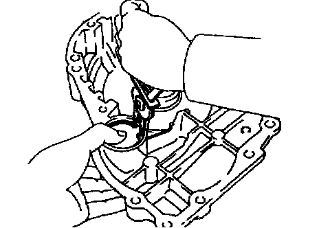
12. REMOVE OVERDRIVE PLANETARY RING GEAR FROM COUNTER DRIVE GEAR
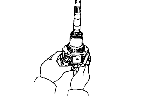
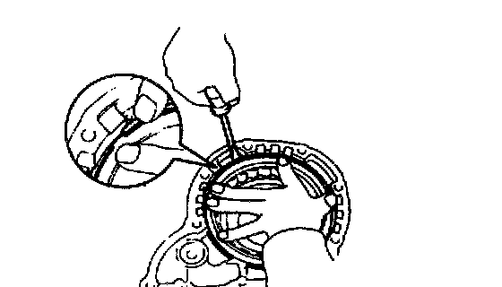
a. While pulling up the ring gear, compress the snap ring with needle-nose pliers and remove it from the groove.
b. Remove the ring gear from the counter drive gear.

13. REMOVE OUTER RACES FROM COUNTER DRIVE GEAR
Drive out the 2 races with a brass bar and hammer.

14. REMOVE SNAP RING FROM COUNTER DRIVE GEAR
Using a screwdriver, remove the snap ring.
Overdrive Planetary Gear Inspection
MEASURE PLANETARY PINION GEAR THRUST CLEARANCE
Using a feeler gauge, measure the planetary pinion gear thrust clearance.
Standard clearance: 0.20 - 0.50 mm (0.0079 - 0.0197 inch)
Counter Drive Gear Assembly

1. INSTALL SNAP RING INTO COUNTER GEAR
Install the snap ring with a screwdriver.

2. INSTALL OUTER RACES INTO COUNTER DRIVE GEAR
Using Special Service Tools (SST), press in the 2 outer races to the gear both side.
SST 09350-32014 (09351-32120, 09351-32150)
HINT: Press in the 2 outer races until they touch the snap ring. Tap the races in straight, so that they do not tilt.

3. INSTALL OVERDRIVE PLANETARY RING GEAR INTO COUNTER DRIVE GEAR
While pushing down the ring gear, squeeze the snap ring end with needle-nose pliers, and install it into the groove.
HINT: When the snap ring is fully seated, the end will be free.

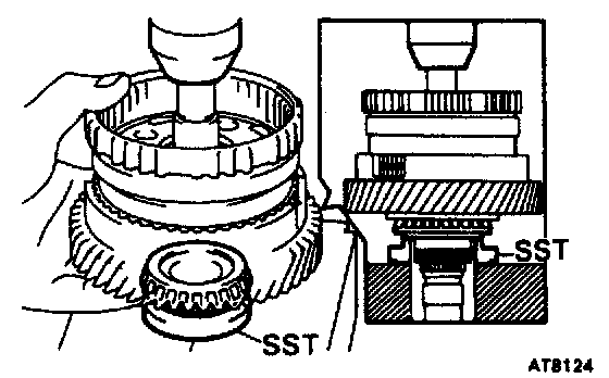
4. INSTALL REAR BEARING
Using SST, press in the bearing onto the shaft.
SST 09350-32014 (09351-32120)
HINT: Press in the bearing until the side surface of the inner race touches the shaft.

5. INSTALL COUNTER DRIVE GEAR AND FRONT BEARING
a. Install the gear onto the shaft, and mesh the ring gear with the planetary pinions.
b. Place the front bearing onto the shaft.
HINT: Hold the ring gear to prevent it from falling.
c. Using SST, press in the bearing until there is slight play between the bearings.
SST 09350-32014 (09351-32120)

6. INSTALL INTERMEDIATE SHAFT BEARING
Using SST, press in the bearing until it slightly touches the front bearing of the counter drive gear.
SST 09350-32014 (09351-32120)
HINT: The counter drive gear can be turned lightly.

7. PLACE NEW LOCKING WASHER AND ADJUSTING NUT ONTO INTERMEDIATE SHAFT
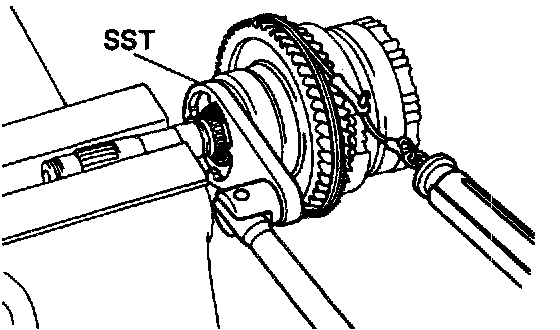
8. ADJUST PRELOAD OF COUNTER DRIVE GEAR
a. Place SST onto the adjusting nut and hold the shaft in a vise with soft jaws.
SST 09350-32014 (09351-32080)
b. Tighten the adjusting nut until the following gear starting load occurs with a tension gauge.
Preload (at starting): 9 - 15 N (920 - 1,530 gf, 2.0 - 3.4 lbs.)
HINT: Turn the counter drive gear right and left several times before measuring the preload.

c. Lock the adjusting nut with one tab on locking washer. Bend the locking washer tab until it is even with the adjusting nut groove.

9. INSTALL PINION SHAFT PLUGS
Install the 4 plugs into the pinion shaft.

10. INSTALL NO.3 OVERDRIVE PLANETARY THRUST WASHER
Install the thrust washer, facing the groove toward the overdrive case.

11. ASSEMBLE OVERDRIVE ONE-WAY CLUTCH
a. Install the one-way clutch into the outer race.
b. Install a retainer on both sides of the one-way clutch.


12. INSTALL OVERDRIVE ONE-WAY CLUTCH INTO HUB
Be sure that the one-way clutch is installed in the correct direction.
13. INSTALL RETAINING PLATE

a. Place the retaining plate into the hub.

b. Install the snap ring with a screwdriver.
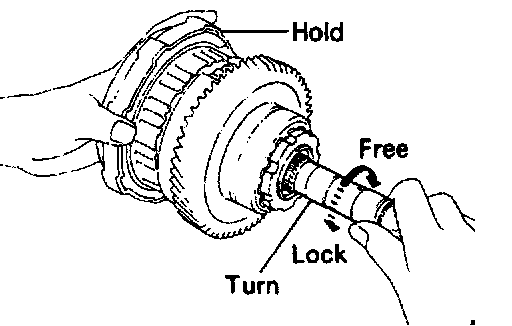
14. CHECK OPERATION OF ONE-WAY CLUTCH
a. While turning the overdrive gear clockwise, install the overdrive direct clutch into the one-way clutch.
b. Hold the overdrive direct clutch and turn the intermediate shaft. The shafts should turn freely clockwise and should lock counterclockwise.
c. Remove the overdrive direct clutch.
Overdrive Case Disassembly
1. REMOVE CO ACCUMULATOR PISTON FROM OVERDRIVE CASE
a. Using snap ring pliers, remove the snap ring.

b. Remove the retaining plate and two springs.
c. Remove the accumulator piston.

d. Remove the 0-ring from the piston.

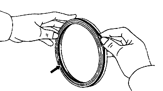
2. REMOVE OIL SEAL RINGS
Spread the 2 rings apart and remove them.
Overdrive Case Inspection
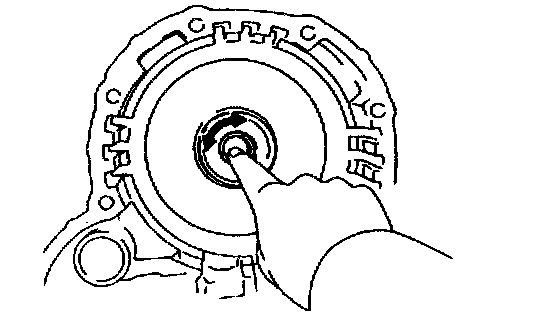
INSPECT OVERDRIVE CASE BEARING
Check that the bearing turns smoothly with your finger.
Overdrive Case Assembly

1. INSTALL OIL SEAL RINGS ON OVERDRIVE (O/D) CASE
Install the oil seal rings to the O/D case groove, then snug them down by squeezing their ends together.
HINT: After installing the oil seal rings, check that they move smoothly.

2. INSTALL CO ACCUMULATOR PISTON OF OVERDRIVE CLUTCH
a. Install a new O-ring to the accumulator piston. Coat the O-ring with Automatic Transmission Fluid (ATF).
b. Install the accumulator piston, 2 springs and plate.
c. Install the snap ring with snap ring pliers.
Overdrive Brake Assembly
1. INSTALL PISTON INTO DRUM
a. Install the new O-rings to the piston. Coat the O-rings with Automatic Transmission Fluid (ATF).

b. Press the piston into the drum, being careful not to damage the O-rings.
2. INSTALL FLANGE, DISCS AND PLATES
a. Install the flange, facing the flat end upward.

b. Install the discs and plates.
Install in order: P=Plate D=Disc
Flange - D - P - P - D - P
HINT: There are 2 different thickness plates, as shown in the illustration.

c. Install the cushion plate facing the rounded end upward.

3. INSTALL PISTON RETURN SPRING
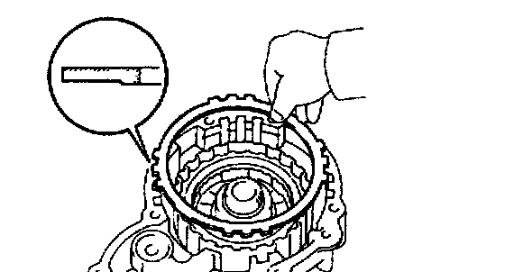
4. INSTALL SNAP RING INTO CASE
Be sure the end gap of the snap ring is not aligned with one of the cutouts.

5. INSTALL OVERDRIVE GEAR ASSEMBLY ONTO CASE
While turning the overdrive gear clockwise, install the overdrive gear assembly to the case. If the overdrive gear assembly is properly installed to the overdrive case, the clearance between them will be about 24 mm (0.94 inch).