Valve Body
VALVE BODY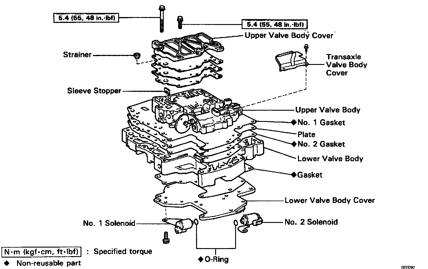
Components
Valve Body Disassembly

1. NOTE THE NUMBERS OF ADJUSTING RINGS
HINT: Count the number of adjusting rings before disassembly of the valve body because the throttle pressure is changed according to the number. (Some of the valve bodies do not have any adjusting rings).
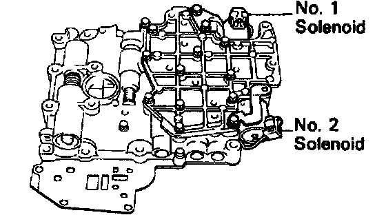
2. REMOVE SOLENOIDS
a. Remove the No.1 and No.2 solenoids.
b. Remove the O-rings from the solenoids.
3. REMOVE UPPER VALVE BODY COVER
Remove the 9 bolts and upper valve body cover.
4. REMOVE STRAINER GASKETS, PLATE AND SLEEVE STOPPER FROM UPPER VALVE BODY

a. Remove the strainer, 2 gaskets and plate.

b. Remove the sleeve stopper.
5. REMOVE BOLTS FROM UPPER VALVE BODY
Remove the 3 bolts from the upper valve body.

6. REMOVE LOWER VALVE BODY COVER
a. Remove the 10 bolts.
b. Remove the lower valve body cover and gasket.

7. REMOVE BOLTS FROM LOWER VALVE BODY
Remove the 3 bolts from lower valve body.

8. LIFT OFF LOWER VALVE BODY AND PLATE AS SINGLE UNIT
Hold the plate to the lower valve body and lift off the lower valve body.
HINT: Be careful that the check balls do not fall out.
9. REMOVE PLATE AND GASKETS
Valve Body Assembly

1. POSITION PLATE AND NEW GASKETS ON LOWER VALVE BODY
Position the new No.2 gasket, the plate and then the new No.1 gasket on the lower valve body.
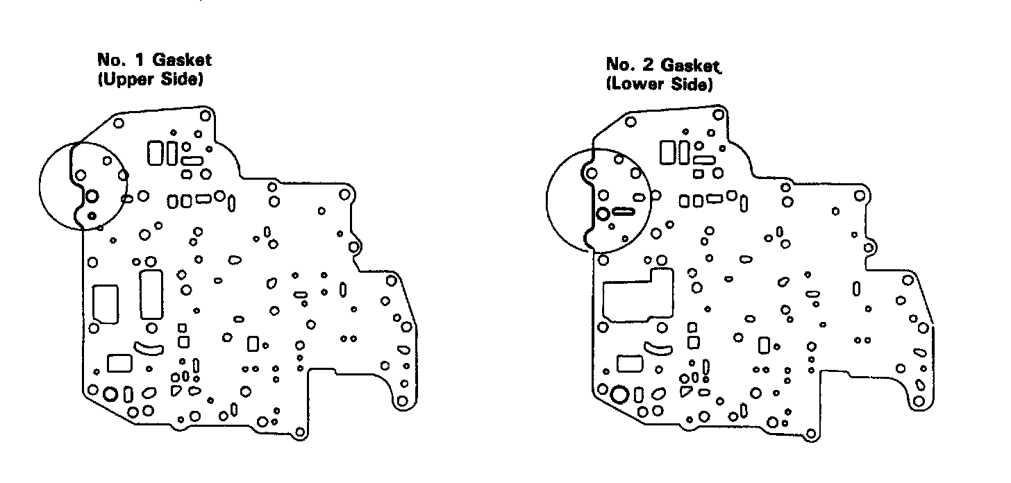
HINT: Since No.1 gasket and No.2 gasket are similar use the illustration shown to discriminate between them.

2. PLACE LOWER VALVE BODY WITH PLATE AND GASKETS ON UPPER VALVE BODY
HINT: Hold the lower valve body, gaskets and plate securely so they do not separate. Align each bolt hole in the valve bodies with the gaskets and plate.

3. INSTALL AND FINGER TIGHTEN BOLTS IN LOWER VALVE BODY TO SECURE UPPER VALVE BODY
Install and finger tighten the 3 bolts.
HINT: Each bolt length (mm, inch) is indicated in the illustration.

4. INSTALL LOWER VALVE BODY COVER
a. Install the lower valve body cover over the new gasket.
b. Install and finger tighten the 10 bolts.
HINT: Each bolt length (mm, inch) is indicated in the illustration.

5. INSTALL AND FINGER TIGHTEN BOLTS IN UPPER VALVE BODY
Install and finger tighten the 3 bolts.
HINT: Each bolt length (mm, inch) is indicated in the illustration.
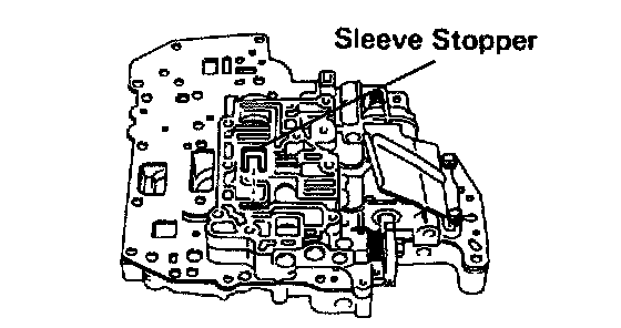
6. INSTALL SLEEVE STOPPER
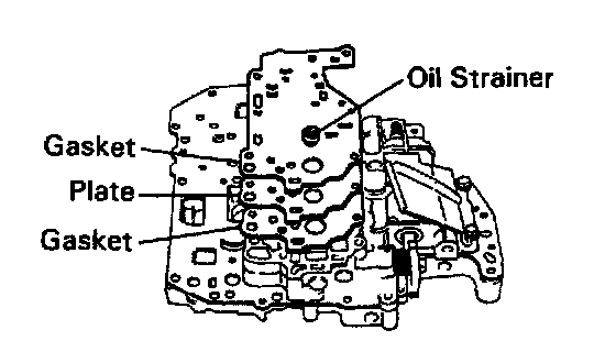
7. INSTALL UPPER VALVE BODY COVER GASKETS, PLATE AND THROTTLE MODULATOR OIL STRAINER
a. Position a new gasket and plate and then another new gasket.
HINT: The gaskets are not identical, but can be installed in any order.
b. Install the oil strainer onto the gasket.

8. INSTALL UPPER VALVE BODY COVER
a. Position the upper valve body cover.
b. Install and finger tighten the 9 bolts.
HINT: Each bolt length (mm, inch) is indicated in the illustration.

9. INSTALL SOLENOIDS
a. Install the new O-rings on the solenoids.
b. Install the No.1 and No.2 solenoids.
c. Install and finger tighten the 3 bolts.
HINT: Each bolt length (mm, inch) is indicated in the illustration.
10. TIGHTEN BOLTS OF UPPER AND LOWER VALVE BODIES

a. Tighten the 16 bolts in the lower valve body.
Torque: 5.4 Nm (55 kgf.cm, 48 inch lbs.)

b. Tighten the 12 bolts in the upper valve body.
Torque: 5.4 Nm (55 kgf.cm, 48 inch lbs.)