Part 2

36. REMOVE SECOND BRAKE PISTON RETURN SPRING

37. REMOVE PLATES, DISCS AND FLANGE

38. REMOVE SECOND BRAKE DRUM GASKET

39. REMOVE SNAP RING HOLDING NO.2 ONE-WAY CLUTCH OUTER RACE TO CASE

40. REMOVE NO.2 ONE-WAY CLUTCH AND REAR PLANETARY GEAR

41. BE CAREFUL WHEN REMOVING THRUST WASHERS FROM BOTH SIDES OF PLANETARY CARRIER

42. REMOVE REAR PLANETARY RING GEAR
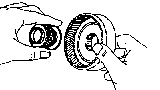
43. REMOVE BEARINGS AND RACES

44. CHECK OPERATION OF FIRST AND REVERSE BRAKE PISTON
Apply compressed air into the case passage and confirm that the piston moves. If the piston does not move, disassemble and inspect.

45. REMOVE SNAP RING HOLDING FLANGE TO CASE
46. REMOVE FLANGES, PLATES AND DISCS
47. TURN TRANSAXLE CASE AROUND
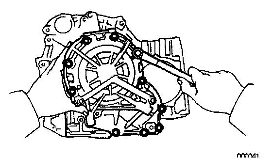
48. REMOVE 11 BOLTS HOLDING OVERDRIVE UNIT TO TRANSAXLE CASE
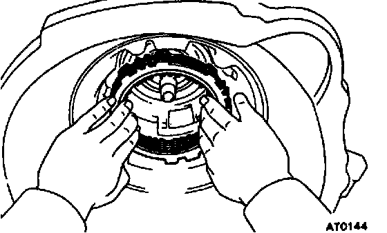
49. REMOVE OVERDRIVE UNIT WITH ALL PARTS
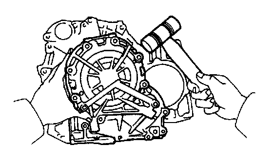
a. Tap on the overdrive case circumference with a plastic hammer to remove the unit from the transaxle case.
b. Remove the overdrive planetary gear and counter gear if they remained in the transaxle.
HINT: The overdrive unit is heavy, so be careful not to drop it.
c. Remove the overdrive brake drum from the transaxle case.

d. Remove the overdrive planetary gear and counter gear if they remain in the transaxle.

50. REMOVE OVERDRIVE CLUTCH APPLY GASKET AND OVERDRIVE BRAKE APPLY GASKET
51. REMOVE PISTON RETURN SPRING

a. Place SST, and compress the return springs evenly by tightening the bolt gradually.
SST 09350-32014 (09351-32040)

b. Using snap ring pliers, remove the snap ring.
c. Remove SST.
d. Remove the return spring from the case.
52. REMOVE FIRST AND REVERSE BRAKE PISTON

a. Apply compressed air into the passage of the case to remove the piston.
HINT: Hold the piston so it is not slanted and blow with the gun slightly away from the oil hole.

b. If the piston does not pop out with compressed air, use needle-nose pliers to remove it.

c. Remove the 2 O-rings from the piston.

53. REMOVE PARKING LOCK PAWL BRACKET

54. REMOVE PARKING LOCK ROD

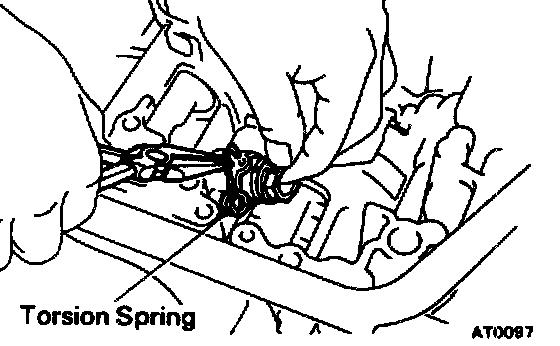
55. REMOVE PIN, SPRING AND PARKING LOCK PAWL
56. REMOVE MANUAL VALVE SHAFT

a. Remove the retaining spring.
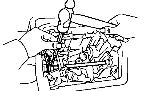
b. Using a hammer and chisel, pry and turn the collar.
c. Using a hammer and punch, drive out the pin.
d. Slide out the shaft and remove the manual valve lever from the case.
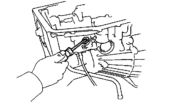
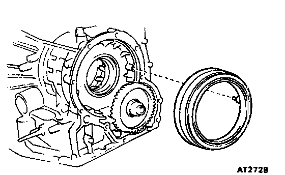
57. REMOVE MANUAL SHAFT OIL SEAL
Remove the oil seal with a screwdriver.
Disassembly of Differential

1. REMOVE CARRIER COVER
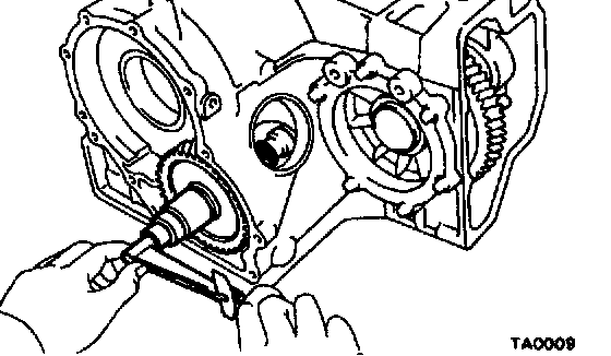
2. MEASURE TOTAL PRELOAD
Using a torque motor, measure the total preload, and note the measurement value.
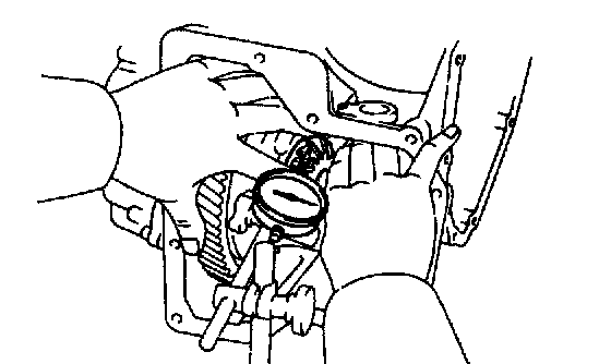
3. MEASURE BACKLASH OF SIDE GEAR
Measure each side gear backlash while holding one pinion toward the case.
Standard backlash: 0.05 - 0.20 mm (0.0020 - 0.0079 inch)

4. REMOVE LH BEARING RETAINER
a. Remove the 6 bolts.
b. Tap the retainer with a plastic hammer to remove it.
c. Remove the 0-ring from the retainer.

5. REMOVE RH SIDE BEARING CAP
Remove the 2 bolts and the side bearing cap.

6. REMOVE DIFFERENTIAL CASE, OUTER RACE AND ADJUSTING SHIM
Remove the differential case, the outer race and the adjusting shim from the case.
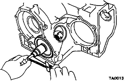
7. MEASURE DRIVE PINION PRELOAD
Using a torque meter, measure the drive pinion preload.
Preload (at starting):
Reused bearing: 0.5 - 0.8 Nm (5 - 8 kgf.cm, 4.3 - 6.9 inch lbs.)
The total preload measured in step 2 minus the drive pinion preload equals 0.1 - 0.2 Nm (1.5 - 2.0 kgf.cm, 1.3 - 1.7 inch lbs.). If the result is not within this specification, the side bearing preload is bad.
8. REMOVE DRIVE PINION CAP

a. Remove the drive pinion cap installation bolt.

b. Using a screwdriver, push out the drive pinion cap.
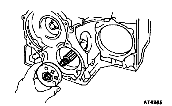
9. REMOVE COUNTER DRIVEN GEAR

a. Using a chisel, loosen the staked part of the nut.
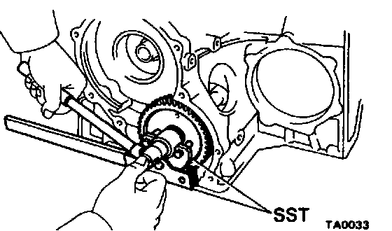
b. Install Special Service Tools (SST) onto the gear.
SST 09350-32014 (09351-32032)
c. Using SST to hold the gear, remove the nut.
SST 09330-00021

d. Using SST, remove the gear and bearing.
SST 09350-32014 (09351-32061)

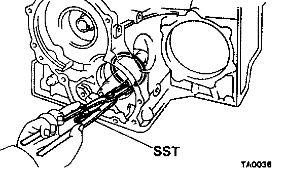
10. REMOVE OUTER RACE FROM CASE
Using SST, remove the outer race.
SST 09350-32014 (09308-10010)

11. REMOVE OIL SLINGER

12. REMOVE SPACER
13. REMOVE ROTOR SENSOR
14. REMOVE DRIVE PINION
a. Using SST, remove the snap ring.
SST 09350-32014 (09351-32050)
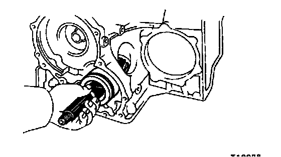
b. Install a brass bar into case hole to tap out the drive pinion.
c. Tap the drive pinion and remove the bearing cage from the bore.

15. REMOVE BEARING CAGE FROM DRIVE PINION
16. REMOVE O-RING FROM BEARING CAGE