Clutch: Service and Repair

REMOVAL
1. REMOVE TRANSAXLE FROM ENGINE

2. REMOVE CLUTCH COVER AND DISC
a. Place matchmarks on the flywheel and clutch cover.
b. Loosen each set bolt one turn at a time until spring tension is released.
c. Remove the set bolts, and pull off the clutch cover with the clutch disc.
NOTICE: Do not drop the clutch disc.

3. REMOVE RELEASE BEARING AND FORK FROM TRANSAXLE
Remove the release bearing together with the fork and then separate them.
INSPECTION
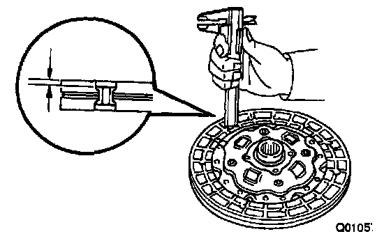
1. INSPECT CLUTCH DISC FOR WEAR OR DAMAGE
Using calipers, measure the rivet head depth.
Minimum rivet depth: 0.3 mm (0.012 inch)
If necessary, replace the clutch disc.

2. INSPECT CLUTCH DISC RUNOUT
Using a dial indicator, check the disc runout.
Maximum runout: 0.8 mm (0.031 inch)
If necessary, replace the clutch disc.
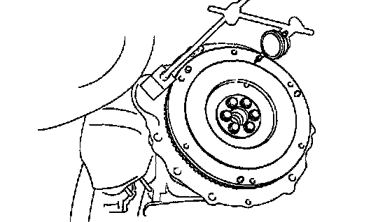
3. INSPECT FLYWHEEL RUNOUT
Using a dial indicator, check the flywheel runout.
Maximum runout: 0.1 mm (0.004 inch)
If necessary, replace the flywheel.
Torque: 88 Nm (900 kgf-cm, 65 ft. lbs.)

4. INSPECT DIAPHRAGM SPRING FOR WEAR
Using calipers, measure the diaphragm spring for depth and width of wear.
Maximum:
A (Depth): 0.5 mm (0.020 inch)
B (Width): 6.0 mm (0.236 inch)
If necessary, replace the clutch cover.
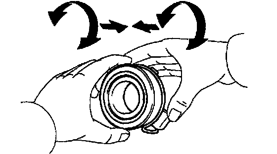
5. INSPECT RELEASE BEARING
Turn the bearing by hand while applying force in the axial direction.
HINT: The bearing is permanently lubricated and requires no cleaning or lubrication.
If necessary, replace the release bearing.
INSTALLATION
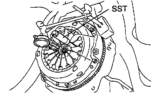
1. INSTALL CLUTCH DISC AND CLUTCH COVER ON FLYWHEEL

a. Insert Special Service Tools (SST) in the clutch disc, and then set them and the clutch cover in position.
SST 09301-00210

b. Align the matchmarks on the clutch cover and flywheel.
c. Torque the bolts on the clutch cover in the order shown.
Torque: 19 Nm (195 kgf-cm, 14 ft. lbs.)
HINT: Temporarily tighten the No.1 and No.2 bolts.
2. CHECK DIAPHRAGM SPRING TIP ALIGNMENT
Using a dial indicator with roller instrument, check the diaphragm spring tip alignment.
Maximum non-alignment: 0.5 mm (0.020 inch)
If alignment is not as specified, using SST, adjust the diaphragm spring tip alignment.
SST 09333-00013

3. APPLY MOLYBDENUM DISULPHIDE LITHIUM BASE GREASE (NLGI NO.2)
a. Apply release hub grease to the following parts:
- Release fork and hub contact point
- Release fork and push rod contact point
- Release fork pivot point
b. Apply clutch spline grease.
- Clutch disc spline
HINT: Recommended grease part number 08887-01706 (100g).
4. INSTALL RELEASE BEARING AND FORK TO TRANSAXLE
Install the bearing to the release fork, and then install them to the transaxle.
5. INSTALL TRANSAXLE TO ENGINE