Part 1

DISASSEMBLY
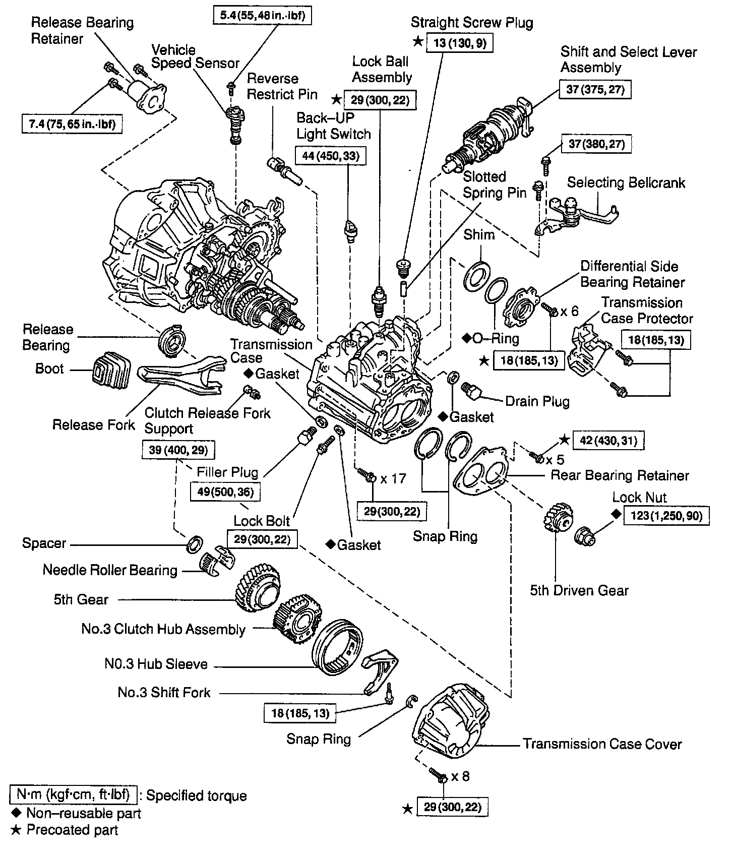
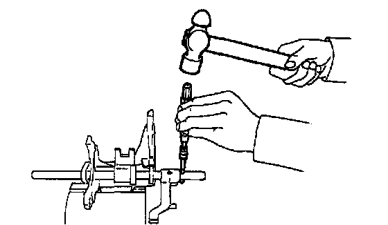
1. REMOVE RELEASE FORK AND BEARING
2. REMOVE BACK-UP LIGHT SWITCH
Torque: 44 Nm (450 kgf-cm, 33 ft. lbs.)
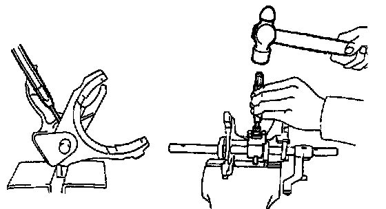
3. REMOVE BOLT AND VEHICLE SPEED SENSOR
Torque: 5.4 Nm (55 kgf-cm, 48 inch lbs.)
4. REMOVE RELEASE BEARING RETAINER
Remove the 3 bolts and retainer.
Torque: 7.4 Nm (75 kgf-cm, 65 inch lbs.)
5. REMOVE SELECTING BELLCRANK
Remove the 2 bolts and selecting bellcrank.
Torque: 37 Nm (380 kgf-cm, 27 ft. lbs.)

6. REMOVE TRANSMISSION CASE COVER
a. Remove the 8 bolts.
Sealant: Part No.08833 - 00080, THREE BOND 1344, LOCTITE 242 or equivalent
Torque: 29 Nm (300 kgf-cm, 22 ft. lbs.)
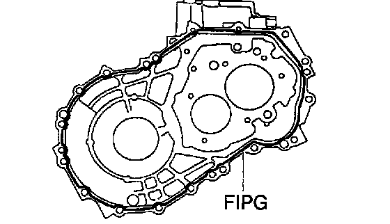
b. Using a plastic hammer, tap the transmission case cover and remove it.
FIPG: Part No. 08826 - 00090, THREE BOND 1281 or equivalent
7. REMOVE LOCK BALL ASSEMBLY
Sealant: Part No.08833 - 00080, THREE BOND 1344, LOCTITE 242 or equivalent
Torque: 29 Nm (300 kgf-cm, 22 ft. lbs.)
8. REMOVE SHIFT AND SELECT LEVER ASSEMBLY
HINT: At the time of reassembly, please refer to the following item. Apply Formed In Place Gasket (FIPG) to the underside of the flanged portion of the control shaft cover.
FIPG: Part No. 08826 - 00090, THREE BOND 1281 or equivalent
Torque: 37 Nm (375 kgf-cm, 27 ft. lbs.)
9. REMOVE OUTPUT SHAFT LOCK NUT
a. Unstake the nut.

b. Engage the gear to the double meshing.

c. Rotate the lock nut clockwise and remove it.
Torque: 123 Nm (1,250 kgf-cm, 90 ft. lbs.)
HINT: The lock nut has LH threads.
d. Disengage the double meshing of the gear.
10. REMOVE NO.3 HUB SLEEVE AND NO.3 SHIFT FORK
a. Remove the No.3 shift fork set bolt.
Torque: 18 Nm (185 kgf-cm, 13 ft. lbs.)
b. Remove the No.3 hub sleeve and No.3 shift fork.

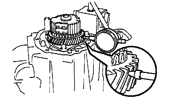
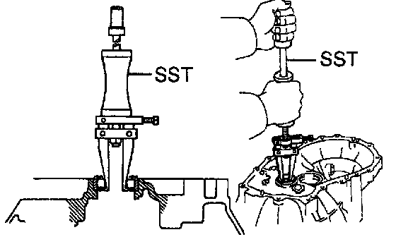
11. REMOVE 5TH DRIVEN GEAR
Using Special Service Tool (SST), remove the 5th driven gear.
SST 09950-40010

HINT: At the time of reassembly, please refer to the following item. Using SST, install the 5th driven gear.
SST 09309-12020

12. MEASURE 5TH GEAR THRUST CLEARANCE
Using a dial indicator, measure the thrust clearance.
Standard clearance: 0.20 - 0.40 mm (0.0079 - 0.0157 inch)
Maximum clearance: 0.45 mm (0.0177 inch)
13. MEASURE 5TH GEAR RADIAL CLEARANCE
Using a dial indicator, measure the radial clearance.
Standard clearance: 0.009 - 0.050 mm (0.0004 - 0.0020 inch)
Maximum clearance: 0.070 mm (0.0028 inch)
If the clearance exceeds the maximum, replace the gear, needle roller bearing or input shaft.
14. REMOVE NO.3 CLUTCH HUB AND 5TH GEAR
a. Using 2 screwdrivers and a hammer, tap out the snap ring.
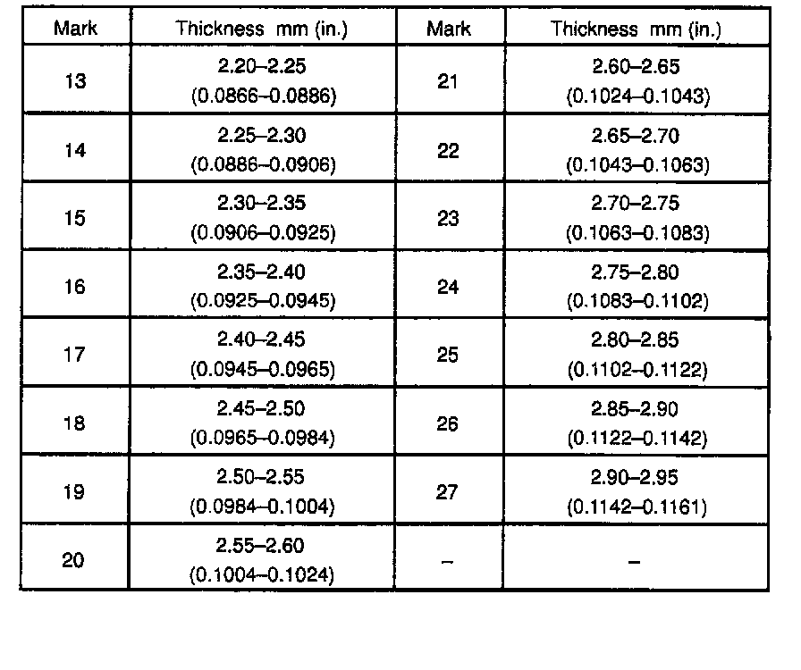
HINT: At the time of reassembly, please refer to the following item. Select a snap ring that allows the minimum axial play.

b. Using SST and a socket wrench, remove the No.3 clutch hub with the synchronizer ring.
SST 09950-30010

HINT: At the time of reassembly, please refer to the following item. Using SST and a press, install the No.3 clutch hub assembly.
SST 09612-22011
c. Remove the 5th gear.
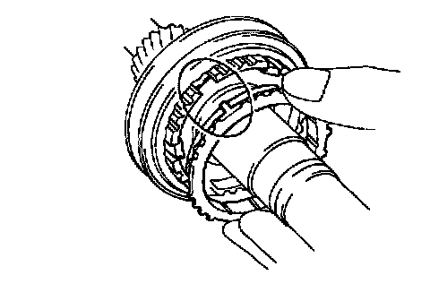
15. REMOVE NEEDLE ROLLER BEARING

16. REMOVE REAR BEARING RETAINER
Remove the 5 bolts and retainer.
Sealant: Part No.08833 - 00070, THREE BOND 1324 or equivalent
Torque: 42 Nm (430 kgf-cm, 31 ft. lbs.)
17. REMOVE BEARING SNAP RING
Using a snap ring expander, remove the 2 snap rings.
HINT: If it is difficult to remove and install the snap rings, pull up the shafts.

18. REMOVE REVERSE IDLER GEAR SHAFT LOCK BOLT AND GASKET
Torque: 29 Nm (300 kgf.cm, 22 ft. lbs.)
19. REMOVE DIFFERENTIAL SIDE BEARING RETAINER AND SHIM
Remove the 6 bolts, retainer and shim.
Sealant: Part No.08833 - 00080, THREE BOND 1344, LOCTITE 242 or equivalent
Torque: 18 Nm (185 kgf-cm, 13 ft. lbs.)
20. REMOVE TRANSMISSION CASE
a. Remove the 17 bolts.
Torque: 29 Nm (300 kgf-cm, 22 ft. lbs.)
b. Using a plastic hammer, tap the transmission case and remove it.
FIPG: Part No. 08833 - 00090, THREE BOND 1281 or equivalent

21. REMOVE REVERSE IDLER GEAR AND SHAFT
a. Pull out the shaft.
b. Remove the idler gear and thrust washer.
22. REMOVE REVERSE SHIFT ARM
a. Shift the fork shaft into reverse.
b. Remove the 2 bolts and pull off the reverse shift arm.
Torque: 18 Nm (185 kgf-cm, 13 ft. lbs.)
23. REMOVE NO.1 SHIFT FORK SHAFT, NO.1 SHIFT HEAD, NO.1 AND NO.2 SHIFT FORKS, REVERSE SHIFT FORK WITH INTERLOCK PIN, INPUT SHAFT ASSEMBLY AND OUTPUT SHAFT ASSEMBLY
24. REMOVE DIFFERENTIAL CASE ASSEMBLY
25. REMOVE MAGNET FROM TRANSAXLE CASE
26. REMOVE NO.2 SHIFT FORK SHAFT
a. Using a hexagon wrench, remove the straight screw plug.
Sealant: Part No. 08833 - 00080, THREE BOND 1344, LOCTITE 242 or equivalent
Torque: 13 Nm (130 kgf-cm, 9 ft. lbs.)
b. Using a pin punch and hammer, drive out the slotted spring pin.
c. Pull out the shaft.
27. SEPARATE NO.1 SHIFT FORK SHAFT, NO.1 SHIFT HEAD, NO.1, NO.2 SHIFT FORKS AND REVERSE SHIFT FORK
a. Mount the shift forks to the vise.
b. Using a pin punch and hammer, drive out the slotted spring pin from the No.1 fork shaft.
c. Using a pin punch and hammer, drive out the slotted spring pin from the No.1 fork shaft, as shown.

d. Separate the No.1 shift fork shaft, No.1 shift head, No.1 and No.2 shift forks and reverse shift fork.

28. REMOVE NO.5 SYNCHRONIZER RING WITH KEY SPRING FROM NO.3 CLUTCH HUB
a. Remove the No.5 synchronizer ring with the key spring from the No.3 clutch hub.
b. Using a screwdriver, remove the snap ring.
HINT: Wrap vinyl tape on the screwdriver to prevent damaging the synchronizer ring.
c. Remove the synchronizer rings.
INSPECTION
1. INSPECT NO.5 SYNCHRONIZER RING
a. Check for wear or damage.
b. Check the braking effect of the synchronizer ring.
Turn the middle No.5 synchronizer ring in one direction while pushing it to the outer No.5 synchronizer ring. Check that the ring locks.
If the braking effect is insufficient, replace the synchronizer ring.

2. INSPECT NO.3 SHIFT FORK AND NO.3 HUB SLEEVE CLEARANCE
Using a feeler gauge, measure the clearance between the hub sleeve and shift fork.
Maximum clearance: 1.0 mm (0.039 inch)
If the clearance exceeds the maximum, replace the shift fork or hub sleeve.
3. IF NECESSARY, REPLACE INPUT SHAFT FRONT BEARING
a. Remove the 2 bolts and transaxle case receiver.
b. Using Special Service Tool (SST) pull out the bearing.
SST 09308-00010

c. Using SST press in a new bearing.
SST 09310-35010
d. Install the transaxle case receiver and torque the 2 bolts.
Torque: 7.4 Nm (75 kgf-cm, 65 inch lbs.)
4. IF NECESSARY, REPLACE OUTPUT SHAFT FRONT BEARING
a. Remove the bolt and bearing lock plate.

b. Using SST, pull out the bearing.
SST 09308-00010

c. Using SST, press in a new bearing.
SST 09310-35010
d. Install the bearing lock plate and torque the bolt.
Torque: 18 Nm (185 kgf-cm, 13 ft. lbs.)

5. IF NECESSARY, REPLACE INPUT SHAFT FRONT OIL SEAL
a. Using a screwdriver, pry out the oil seal.
b. Using SST, drive in a new oil seal.
SST 09608-00081, 09950-70010 (09951-07150)
Drive in depth: 0 - 0.5 mm (0 - 0.020 inch)
c. Coat the lip of the oil seal with Multipurpose (MP) grease.

6. IF NECESSARY, REPLACE REVERSE RESTRICT PIN
a. Using a hexagon wrench, remove the straight screw plug.
b. Using a pin punch and hammer, drive out the slotted spring pin.
c. Replace the reverse restrict pin.
d. Using a pin punch and hammer, drive in the slotted spring pin.
Drive in depth: 13.5 ± 0.5 mm (0.531 ± 0.020 inch)
e. Apply sealant to the plug threads.
Sealant: Part No.08833 - 00080, THREE BOND 1344, LOCTITE 242 or equivalent
f. Using a hexagon wrench, install and torque the straight screw plug.
Torque: 13 Nm (130 kgf-cm, 9 ft. lbs.)
REASSEMBLY
Reassembly is in the reverse order of disassembly .
NOTICE: When working with Formed In Place Gasket (FIPG) material, you must observe the following items.
^ Using a razor blade and gasket scraper, remove all the old FIPG material from the gasket surfaces.
^ Thoroughly clean all components to remove all the loose material.
^ Clean both sealing surfaces with a non-residue solvent.
^ Apply FIPG in an approx. 1 mm (0.04 inch) wide bead along the sealing surface.
^ Parts must be assembled within 10 minutes of application. Otherwise, the FIPG material must be removed and reapplied.
HINT: Coat all of the sliding and rotating surfaces with gear oil before reassembly.

INPUT SHAFT
Disassembly

1. INSPECT 3RD AND 4TH GEARS THRUST CLEARANCE
Using a feeler gauge, measure the clearance.
Standard clearance:
3rd gear: 0.10 - 0.25 mm (0.0039 - 0.0098 inch)
4th gear: 0.20 - 0.45 mm (0.0079 - 0.0177 inch)
Maximum clearance:
3rd gear: 0.30 mm (0.0118 inch)
4th gear: 0.50 mm (0.0197 inch)

2. INSPECT 3RD AND 4TH GEARS RADIAL CLEARANCE
Using a dial indicator, measure the radial clearance between the gear and shaft.
Standard clearance: 0.009 - 0.053 mm (0.0004 - 0.0021 inch)
Maximum clearance: 0.070 mm (0.0028 inch)
If the clearance exceeds the maximum, replace the gear, needle roller bearing or shaft.
3. REMOVE SNAP RING
Using 2 screwdrivers and a hammer, tap out the snap ring.

4. REMOVE REAR BEARING, 4TH GEAR, NEEDLE ROLLER BEARING, SPACER AND SYNCHRONIZER RING FROM INPUT SHAFT
a. Using SST and a press, remove the 4th gear and rear bearing.
SST 09950-00020
b. Remove the needle roller bearings, spacer and synchronizer ring.
5. REMOVE SNAP RING
Using a snap ring expander, remove the snap ring.

6. REMOVE NO.2 HUB SLEEVE ASSEMBLY, 3RD GEAR SYNCHRONIZER RING AND NEEDLE ROLLER BEARING
Using SST and a press, remove the No.2 hub sleeve, 3rd gear, synchronizer ring and needle roller bearings.
SST 09950-00020
NOTICE: Be careful not to mistake the 3rd gear synchronizer ring for the 4th gear synchronizer ring.

7. REMOVE NO.2 HUB SLEEVE, SHIFTING KEY AND SPRING FROM NO.2 CLUTCH HUB
Using a screwdriver, remove the 3 shifting keys and 2 springs from the No.2 clutch hub.
Inspection

1. INSPECT SYNCHRONIZER RING
a. Check for wear or damage.
b. Check the braking effect of the synchronizer ring. Turn the synchronizer ring in one direction while pushing it to the gear cone. Check that the ring locks.
If the braking effect is insufficient, apply a small amount of the fine lapping compound between the synchronizer ring and gear cone. Lightly rub the synchronizer ring and gear cone together.
NOTICE: Ensure the fine lapping compound is completely washed off after rubbing.
c. Check again the braking effect of the synchronizer ring.

d. Using a feeler gauge, measure the clearance between the synchronizer ring back and gear spline end.
Minimum clearance: 0.6 mm (0.024 inch)
If the clearance is less than the minimum, replace the synchronizer ring, and apply a small amount of the fine lapping compound on gear cone.
NOTICE: Ensure the fine lapping compound is completely washed off after rubbing.

2. INSPECT NO.2 SHIFT FORK AND HUB SLEEVE CLEARANCE
Using a feeler gauge, measure the clearance between the hub sleeve and shift fork.
Maximum clearance: 1.0 mm (0.039 inch)
If the clearance exceeds the maximum, replace shift fork or hub sleeve.

3. INSPECT INPUT SHAFT
a. Check the input shaft for wear or damage.
b. Using a micrometer, measure the outer diameter of the input shaft journal surface.
Minimum outer diameter:
Part A, 26.970 mm (1.0618 inch)
Part B: 32.470 mm (1.2783 inch)
Part C: 33.090 mm (1.3028 inch)
Part D: 29.970 mm (1.1799 inch)
If the outer diameter is less than the minimum, replace the input shaft.

c. Using a dial indicator, check the shaft runout.
Maximum runout: 0.05 mm (0.0020 inch)
If the runout exceeds the maximum, replace the input shaft.
Reassembly
HINT: Coat all of the sliding and rotating surfaces with gear oil before reassembly.

1. INSTALL NO.2 CLUTCH HUB INTO HUB SLEEVE
a. Install the clutch hub and shifting keys to the hub sleeve.
b. Install the shifting key springs under the shifting keys.
NOTICE: Position the key springs so that their end gaps are not aligned.
2. INSTALL 3RD GEAR, NEEDLE ROLLER BEARING, SYNCHRONIZER RING AND NO.2 HUB SLEEVE ASSEMBLY TO INPUT SHAFT
a. Apply gear oil to the needle roller bearings.

b. Place the synchronizer ring (for the 3rd gear) on the gear and align the ring slots with the shifting keys.
NOTICE: Do not install the synchronizer ring for 4th gear.

c. Using a press, install the 3rd gear and No.2 hub sleeve.

3. INSTALL SNAP RING

a. Select a snap ring that allows the minimum axial play.
b. Using a snap ring expander, install the snap ring.
4. INSPECT 3RD GEAR THRUST CLEARANCE
5. INSTALL SYNCHRONIZER RING, NEEDLE ROLLER BEARING, SPACER, 4TH GEAR AND REAR BALL BEARING
a. Apply gear oil to the needle roller bearings.

b. Install the spacer and needle roller bearings.
c. Place the synchronizer ring on the gear.
HINT: Align the ring slots with the shifting keys and the ring projections with the hub slots.

d. Using SST and a press, install the rear ball bearing.
SST 09608-00071

6. INSTALL SNAP RING

a. Select a snap ring that allows the minimum axial play.
b. Using a screwdriver and hammer, tap in the snap ring.
7. INSPECT 4TH GEAR THRUST CLEARANCE