Removal and Installation

REMOVAL
1. REMOVE BATTERY AND AIR CLEANER CASE ASSEMBLY WITH AIR HOSE

2. w/Cruise Control: REMOVE CRUISE CONTROL ACTUATOR
a. Disconnect the connector.
b. Remove the 3 bolts and cruise control actuator with the bracket.
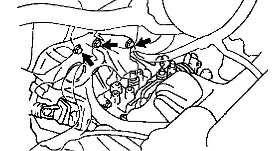
3. REMOVE STARTER
a. Disconnect the connector and wire from the starter.
b. Remove the 2 bolts and starter.
Torque: 39 Nm (400 kgf-cm, 29 ft. lbs.)
4. REMOVE CLUTCH RELEASE CYLINDER AND LINE CLAMP
a. Remove the 2 bolts and release cylinder.
Torque: 12 Nm (120 kgf-cm, 9 ft. lbs.)
b. Remove the 2 bolts and line clamps.
5. DISCONNECT GROUND CABLE
Torque: 19 Nm (195 kgf-cm, 14 ft. lbs.)
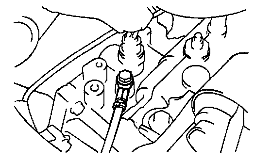
6. DISCONNECT BACK-UP LIGHT SWITCH AND VEHICLE SPEED SENSOR CONNECTORS
7. DISCONNECT CONTROL CABLE
a. Remove the 2 clips and washers.
b. Remove the 2 clips from the cables.
8. REMOVE 3 TRANSAXLE MOUNTING BOLTS

9. REMOVE ENGINE LEFT MOUNTING BOLT AND NUT
Remove the bolt and 2 nuts of engine left mounting on the upper side.
Torque: 64 Nm (650 kgf-cm, 47 ft. lbs.)
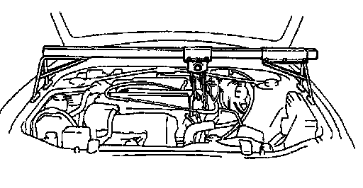
10. INSTALL ENGINE SUPPORT FIXTURE
11. REMOVE FRONT WHEEL
Torque: 103 Nm (1,050 kgf-cm, 76 ft. lbs.)
12. RAISE VEHICLE
NOTICE: Make sure that the vehicle is securely supported.
13. REMOVE LH AND RH ENGINE UNDER COVERS
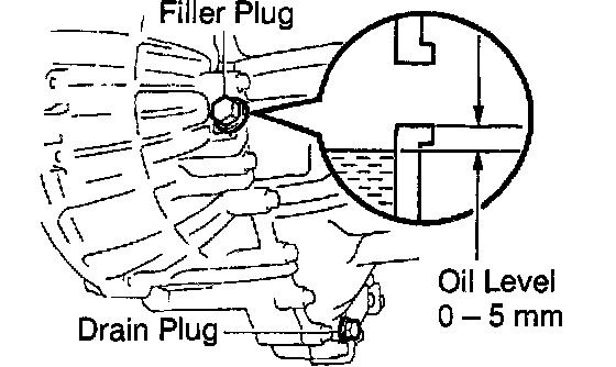
14. DRAIN TRANSAXLE OIL
Oil grade: API GL-4 or GL-5
Viscosity: SAE 75W-90
Capacity: 2.2 liters (2.3 US qts., 1.9 Imp. qts.)
Torque: 49 Nm (500 kgf-cm, 36 ft. lbs.)
15. REMOVE LH AND RH FRONT DRIVE SHAFTS

16. REMOVE FRONT EXHAUST PIPE
a. Remove the 3 nuts and exhaust front pipe with the gasket.
Torque: 62 Nm (630 kgf-cm, 46 ft. lbs.)
b. Remove the 2 nuts, bolts and gasket.
Torque: 43 Nm (440 kgf-cm, 32 ft. lbs.)
c. Remove the nut, 4 bolts and exhaust pipe support bracket.
Torque: 19 Nm (195 kgf-cm, 14 ft. lbs.)

17. REMOVE ENGINE FRONT MOUNTING INSULATOR AND BRACKET
a. Remove the grommet.
b. Remove the nut and through bolt.
Torque: Bolt A: 87 Nm (890 kgf-cm, 64 ft. lbs.)
c. Remove the 4 bolts, insulator and bracket.
Torque:
Bolt B: 77 Nm (790 kgf-cm, 57 ft. lbs.)
Bolt C: 80 Nm (820 kgf-cm, 59 ft. lbs.)

18. REMOVE ENGINE REAR MOUNTING INSULATOR AND BRACKET
a. Remove the 2 grommets.
b. Remove the through bolt.
Torque: Bolt A: 87 Nm (890 kgf-cm, 64 ft. lbs.)
c. Remove the 4 bolts, 2 nuts, insulator and bracket.
Torque:
Bolt B: 77 Nm (790 kgf-cm, 57 ft. lbs.)
Bolt and Nut C: 54 Nm (550 kgf-cm, 40 ft. lbs.)

19. REMOVE ENGINE LEFT MOUNTING BOLT
Remove the bolt of engine left mounting on the lower side.
Torque: 64 Nm (650 kgf-cm, 47 ft. lbs.)
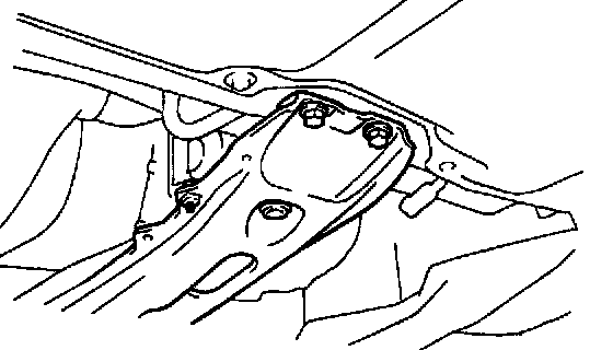
20. REMOVE CENTER MEMBER
a. Remove the bolt and pipe bracket.
b. Remove the 2 bolts and center member.
Torque: 52 Nm (530 kgf-cm, 38 ft. lbs.)
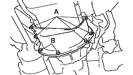
21. REMOVE STIFFENER PLATE
Remove the 6 bolts, nut and stiffener plate.
Torque:
Bolt and Nut A: 43 Nm (440 kgf-cm, 32 ft. lbs.)
Bolt B: 21 Nm (210 kgf-cm, 15 ft. lbs.)
22. JACK UP TRANSAXLE SLIGHTLY
Using a transmission jack, support the transaxle.

23. REMOVE TRANSAXILE
a. Remove the transaxle mounting bolts.
Torque:
12 mm bolt: 64 Nm (650 kgf-cm, 47 ft. lbs.)
10 mm bolt: 46 Nm (470 kgf-cm, 34 ft. lbs.)
b. Lower the engine left side and remove the transaxle from the engine.
HINT: At the time of installation, please refer to the following item. Align the input shaft with the clutch disc and install the transaxle to the engine.
INSTALLATION
Installation is in the reverse order of removal.
HINT: After installation, check and inspect items as follows.
^ Front wheel alignment.
^ Do the road test.