Assembly
REASSEMBLYHINT:
- Thoroughly clean all parts to be assembled.
- Before installing the parts, apply new engine oil to all sliding and rotating surfaces.
- Replace all gaskets, O-rings and oil seals with new parts.
1. Assemble piston and connecting rod.


a. Using a small screwdriver, install a new snap ring on one side of the piston pin hole.
b. Gradually heat the piston to 80 - 90°C (176 - 194°F).

c. Coat the piston pin with engine oil.
d. Align the front marks of the piston and connecting rod, and push in the piston pin with your thumb.

e. Using a small screwdriver, install a new snap ring on the other side of the piston pin hole.

2. Install piston rings.
a. Install the oil ring expander and 2 side rails by hand.
b. Using a piston ring expander, install the No.2 and No.1 piston rings with the code mark facing upward.
Code mark:
No.1: 1N or T
No.2: 2N or 2T

c. Position the piston rings so that the ring ends are as shown.
NOTICE: Do not align the ring ends.

3. Install bearings.
a. Align the bearing claw with the groove of the connecting rod or connecting cap.
b. Install the bearings in the connecting rod and connecting rod cap.

4. Install main bearings.
HINT:
- Main bearings come in widths of 19.2 mm (0.756 inch) and 22.9 mm (0.902 inch). Install the 22.9 mm (0.902 inch) bearings in the No.3 cylinder block journal position with the main bearing cap. Install the 19.2 mm (0.756 inch) bearings in the other positions.
- Upper bearings have an oil groove and oil holes; lower bearings do not.

a. Align the bearing claw with the claw groove of the cylinder block, and push in the 5 upper bearings.

b. Align the bearing claw with the claw groove of the main bearing cap, and push in the 5 lower bearings.
HINT: A number is marked on each main bearing cap to indicate the installation position.
5. Install upper thrust washers.
Install the 2 thrust washers under the No.3 journal position of the cylinder block with the oil grooves facing outward.
6. Place crankshaft on cylinder block.
7. Install main bearing caps and lower thrust washers.

a. Install the 2 thrust washers on the No.3 bearing cap with the grooves facing outward.

b. Install the 5 main bearing caps in their proper locations.
HINT: Each bearing cap has a number and front mark.
Main Bearing Cap Bolt Installation:

c. Apply a light coat of engine oil on the threads and under the heads of the main bearing cap bolts.
d. Install and uniformly tighten the 10 bolts of the main bearing cap in several passes, in the sequence shown.
Torque: 59 Nm (43 ft. lbs.)
e. Check that the crankshaft turns smoothly.
8. Check crankshaft thrust clearance.
9. Install piston and connecting rod assembles.

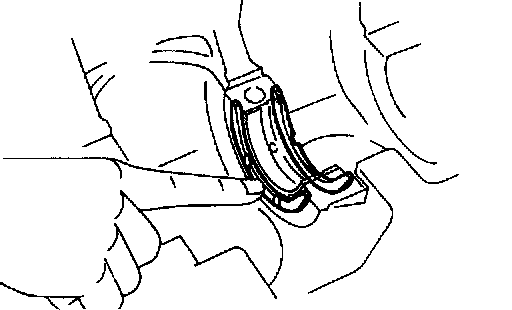
a. Cover the connecting rod bolts with a short piece of hose to protect the crankshaft from damage.

b. Using a piston ring compressor, push the correctly numbered piston and connecting rod assemblies into each cylinder with the front mark of the piston facing forward.

10. Place connecting rod cap on connecting rod.
a. Match the numbered connecting rod cap with the connecting rod.
b. Install the connecting rod cap with the front mark facing forward.
11. Install connecting rod cap nuts.

HINT:
- The cap nuts are tightened in 2 progressive steps (steps (b) and (d)).
- If any one of the connecting rod bolts is broken or deformed, replace it.
a. Apply a light coat of engine oil on the threads and under the nuts of the connecting rod cap.
b. Install and alternately tighten the 2 cap nuts in several passes.
Torque: 25 Nm (18 ft. lbs.)
If any one of the cap nuts does not meet the torque specification, replace the connecting rod bolt and cap nut as a set.

c. Mark the front of the cap nut with the paint.
d. Retighten the cap nuts 90° as shown.
e. Check that the painted mark is now at a 90° angle to the front.
f. Check that the crankshaft turns smoothly.
12. Check connecting rod thrust clearance.

13. Install rear oil seal retainer.
Install a new gasket and the retainer with the 6 bolts.
Torque: 13 Nm (9 ft. lbs.)
Drive Belt Adjusting Bar, Water Pump and Cover Installation:
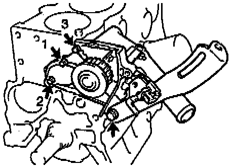
14. Install water pump, water pump cover assembly and generator drive belt adjusting bar.
a. Install a new O-ring to the water pump cover.
b. Install the water pump with the 3 bolts. Tighten the bolts in the sequence shown.
Torque: 7.8 Nm (69 inch lbs.)
c. Install the adjusting bar with the bolt.
Torque: 27 Nm (20 ft. lbs.)
15. Install knock sensor 1.
16. Install oil cooler.
17. Install oil pump and and oil pan.
18. Install cylinder head.
19. Install timing belt and pulleys.
20. Install Power Steering (PS) pump bracket.
Install the PS pump bracket with the 3 bolts.
Torque: 43 Nm (32 ft. lbs.)
21. Disconnect engine from engine stand.