Cylinder Head Removal
REMOVAL1. Remove RH engine under cover.
2. Drain engine coolant.
3. Remove air cleaner cap and case.
4. Remove distributor.
5. Remove generator.
6. Remove front exhaust pipe.
7. Remove exhaust manifold and front Three-Way Catalytic Converter (TWC) assembly.

a. Disconnect these connectors:
- Oxygen sensor (bank 1 sensor 1 ) connector
- Oxygen sensor (bank 1 sensor 2) connector
b. Remove the bolt, nut and LH exhaust manifold stay.
c. Remove the 5 bolts and manifold upper heat insulator.
d. Remove the 2 bolts, 2 nuts and RH exhaust manifold stay.

e. Remove the 6 nuts, the exhaust manifold and TWC assembly.

8. Remove oxygen sensor (Bank 1 Sensor 1) from exhaust manifold.
Remove the 2 nuts, oxygen sensor and gasket.
9. Remove oxygen sensor (Bank 1 Sensor 2) from front TWC.

10. Separate exhaust manifold and front TWC.
a. Remove the 5 bolts and lower manifold heat insulator.
b. Remove the 8 bolts and 2 TWC heat insulators.
c. Remove the 3 bolts, 2 nuts, TWC, gasket, retainer and cushion.
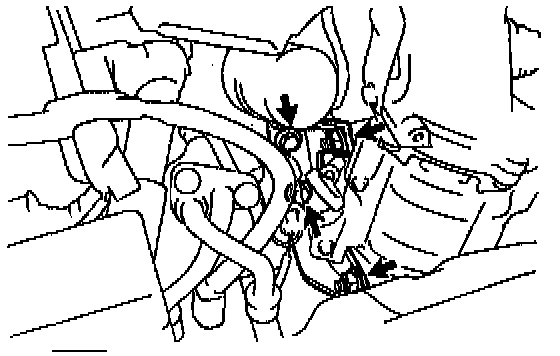
11. Disconnect oil pressure switch connector.

12. Remove water outlet.
a. Disconnect these connectors:
- Engine Coolant Temperature (ECT) sensor connector
- ECT sender gauge connector
b. Disconnect these hoses from the water outlet:
1) Radiator hose
2) Water bypass pipe hose
3) Heater water hose
4) Vacuum hose (from P port of throttle body) from upper port of Thermal Vacuum Valve (TVV) for Evaporative Emission (EVAP)
5) Vacuum hose (from charcoal canister) from lower port of TVV for EVAP
6) Idle Air Control (IAC) valve water bypass hose
c. Remove the 2 nuts, water outlet and gasket.

13. Remove water bypass pipe.
a. Remove the bolt, 2 nuts and oil cooler heat protector.
b. Disconnect these hoses:
1) IAC valve water bypass hose from water bypass pipe.
2) Heater water hose from water bypass pipe.
3) 2 oil cooler water bypass hoses from oil cooler.
c. Remove the 2 bolts and 2 nuts.

d. Disconnect the water bypass pipe from the water pump cover, and remove the water bypass pipe.
e. Remove the gasket and O-ring.
14. Remove throttle body.
15. Disconnect hoses.

Disconnect these hoses:
1) Manifold Absolute Pressure (MAP) sensor vacuum hose from gas filter on manifold.
2) Brake booster vacuum hose from intake manifold.
16. Remove Exhaust Gas Recirculation (EGR) valve and vacuum modulator.

a. Disconnect the EVAP hose from the charcoal canister.
b. Disconnect the hose clamp from the bracket on the air tube.

c. Disconnect the 2 vacuum hoses from the Vacuum Switching Valve (VSV) for the EGR.

d. Disconnect the vacuum modulator from the clamp on the intake manifold.
e. Loosen the union nut of the EGR pipe, and remove 2 nuts, the EGR valve, vacuum modulator, vacuum hoses assembly and gasket.
17. Remove intake manifold stay.
Remove the bolt, nut and intake manifold stay.

18. Disconnect A/T throttle control cable from intake manifold.
Disconnect the control cable from the clamp on the rear side of the intake manifold.
19. Remove air tube.
a. Disconnect these hoses:

1) 2 Power Steering (PS) air hoses from air tube

2) PS air hose from intake manifold
3) Air hose from fuel pressure regulator

b. Remove the 2 bolts, hose bracket (for EGR) and air tube.

20. Disconnect knock sensor 1 connector.
21. Disconnect ground wires.
Remove bolt, and disconnect the 2 ground wires from the intake manifold.
22. Remove VSV for EGR.
a. Disconnect the VSV connector.
b. Remove the bolt and VSV.

23. Disconnect Positive Crankcase Ventilation (PCV) hose from intake manifold.
24. Disconnect accelerator, A/T throttle control cables and bracket from intake manifold and clamps.
a. Remove the 2 bolts, and disconnect cable bracket from the intake manifold.
b. Disconnect the control cables from the 4 clamps.
25. Disconnect engine wire.

a. Disconnect the the engine wire protector from the bracket on the starter.

b. Disconnect the Vehicle Speed Sensor (VSS) sensor connector.
c. Remove the bolt, and disconnect the the engine wire protector from the LH side of the intake manifold.
d. Disconnect the 4 injector connectors.

e. Disconnect the engine wire protector from the 2 brackets on the front side of the intake manifold.

f. Disconnect the engine wire protector from the 2 mounting bolts of the No.2 timing belt cover in the sequence shown.

26. Disconnect fuel inlet hose from delivery pipe.
Remove the union bolt and 2 gaskets, and disconnect the inlet hose from the delivery pipe.
27. Disconnect fuel return hose from return pipe.

28. Remove intake manifold.
a. Remove the 6 bolts and 2 nuts.
b. Disconnect the engine wire between the intake manifold and cylinder head.
c. Remove the intake manifold and gasket.

29. California only: Remove air hose for air assist system.
Disconnect the air hose from the cylinder head port, and remove the air hose.
30. Remove delivery pipe and injectors.

a. Remove the 2 bolts and delivery pipe together with the 4 injectors.
NOTICE: Be careful not to drop the injectors when removing the delivery pipe.
b. Remove the 4 insulators (except California) and 2 spacers from the cylinder head.
c. Pull out the 4 injectors from the delivery pipe.
d. California: Remove the 2 O-rings, insulator and grommet from each injector.
e. Except California: Remove the O-ring and grommet from each injector.
31. Disconnect timing belt from camshaft timing pulley.
32. Remove camshaft timing pulley.

33. Remove NO.1 idler pulley and tension spring.
Remove the bolt, pulley and tension spring.
34. Remove NO.3 timing belt cover.
Remove the 3 bolts and timing and cover.

NOTICE:
- Support the timing belt, so the meshing of the crankshaft timing pulley and timing belt does not shift.
- Be careful not to drop anything inside the timing belt cover.
- Do not allow the belt to come into contact with oil, water or dust.
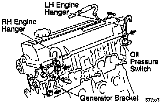
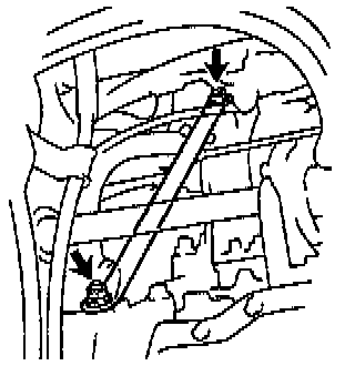
35. Remove engine hangers and generator bracket.
a. Remove the 3 bolts, the generator bracket and RH engine hanger assembly.
b. Remove the bolt and LH engine hanger.
36. Remove oil pressure switch.

37. Remove cylinder head cover.
Remove the 4 nuts, grommets, head cover and gasket.
HINT: Arrange the grommets in the correct order, so that they can be reinstalled into their original positions. This minimizes any possibility of oil leakage due to reuse of the grommets in different positions.
38. Remove high-tension cord clamp, PCV valve and hoses from cylinder head cover.
a. Remove the bolt and high-tension cord clamp.
b. Remove the PCV valve, hose assembly and grommet.
c. Remove the PCV hose.
39. Remove camshafts.
NOTICE: Since the thrust clearance of the camshaft is small, the camshaft must be kept level while it is being removed. If the camshaft is not kept level, the portion of the cylinder head receiving the shaft thrust may crack or be damaged, causing the camshaft to seize or break. To avoid this, the following steps should be carried out.
Exhaust Camshaft:

a. Set the knock pin of the intake camshaft at 10 - 45° Before Top Dead Center (BTDC) of camshaft angle.
HINT: The above angle allows No.2 and No.4 cylinder cam lobes of the exhaust camshaft to push their valve lifters evenly.
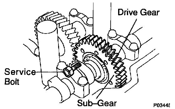
b. Secure the exhaust camshaft sub-gear to drive gear with a service bolt.
Recommended service bolt:
Thread diameter 6 mm
Thread pitch 1.0 mm
Bolt length 16 - 20 mm (0.63 - 0.79 inch)
HINT: When removing the camshaft, make sure that the torsional spring force of the sub-gear has been eliminated by the above operation.

c. Remove the 2 bolts and rear bearing cap.
Exhaust Camshaft Bearing Cap Removal Sequence:

d. Uniformly loosen and remove the 6 bolts on the No.1, No.2 and No.4 bearing caps in several passes, in the sequence shown.
NOTICE: Do not remove the No.3 bearing cap bolts at this stage.
e. Remove the No.1, No.2 and No.4 bearing caps.

f. Alternately loosen and remove the 2 bolts on the No.3 bearing cap.
HINT:
- As the 2 No.3 bearing cap bolts are loosened, make sure that the camshaft is lifted out straight and level.
- If the camshaft is not being lifted out straight and level, retighten the 2 No.3 bearing cap bolts. Then reverse the order of above steps from (f) to (a) and reset the knock pin of the intake camshaft at 10 - 45° BTDC, and repeat steps from (b) to (f) once again.
NOTICE: Do not pry on or attempt to force the camshaft with a tool or other object.
g. Remove the No.3 bearing cap and exhaust camshaft.

Intake Camshaft:
a. Set the knock pin of the intake camshaft at 80 - 115° BTDC of camshaft angle.
HINT: The above angle allows the No.1 and No.3 cylinder cam lobes of intake camshaft to push their valve lifters evenly.

b. Remove the 2 bolts, front bearing cap and oil seal.
Intake Camshaft Bearing Cap Removal Sequence:

c. Uniformly loosen and remove the 6 bolts on the No.1, No.3 and No.4 bearing caps in several passes, in the sequence shown.
NOTICE: Do not remove the No.2 bearing cap bolts at this stage.
d. Remove the No.1, No.3 and No.4 bearing caps.

e. Alternately loosen and remove the 2 bolts on the No.2 bearing cap.
HINT:
- As the 2 No.2 bearing cap bolts are loosened, make sure that the camshaft is lifted out straight and level, after breaking adhesion on the front bearing cap.
- If the camshaft is not being lifted out straight and level, retighten the 2 No.2 bearing cap bolts. Reverse the order of above steps from (e) to (a) and reset the knock pin of the intake camshaft at 80 - 115° BTDC, and repeat steps from (b) to (e) once again.
NOTICE: Do not pry on or attempt to force the camshaft with a tool or other object.
f. Remove the No.2 bearing cap and camshaft.
40. Disassemble exhaust camshaft.

a. Mount the camshaft in a vise.
NOTICE: Be careful not to damage the camshaft.

b. Using Special Service Tool (SST) 09960 - 10010 (09962 - 01000, 09963 - 00500 or equivalent, turn the sub-gear clockwise, and remove the service bolt.

c. Using snap ring pliers, remove the snap ring.

d. Remove these parts:
1) Wave washer
2) Camshaft sub-gear
3) Camshaft gear spring
41. Remove cylinder head.
Cylinder Head Removal:

a. Uniformly loosen and remove the 10 cylinder head bolts in several passes, in the sequence shown.
NOTICE: Cylinder head warpage or cracking could result from removing bolts in incorrect order.

b. Lift the cylinder head from the dowels on the cylinder block, and place the cylinder head on wooden blocks on a bench.
HINT: If the cylinder head is off, pry between the cylinder head and cylinder block with a screwdriver.
NOTICE: Be careful not to damage the contact surfaces of the cylinder head and cylinder block.