Part 2
12. Inspect camshaft journals.
Using a micrometer, measure the journal diameter.
Journal diameter: 26.959 - 26.975 mm (1.0614 - 1.0620 inch)
If the journal diameter is not as specified, check the oil clearance.
13. Inspect camshaft gear spring.

Using a vernier caliper, measure the free distance between the spring ends.
Free distance: 22.5 - 22.9 mm (0.886 - 0.902 inch)
If the free distance is not as specified, replace the gear spring.
14. Inspect camshaft journal oil clearance.
a. Clean the bearing caps and camshaft journals.
b. Check that bearings for flaking and scoring.
If the bearings are damaged, replace the bearing caps and cylinder head as a set.
c. Place the camshafts on the cylinder head.

d. Lay a strip of Plastigage across each of the camshaft journals.
e. Install the bearing caps.
NOTICE: Do not turn the camshaft.
f. Remove the bearing caps.

g. Measure the Plastigage at its widest point.
Standard oil clearance: 0.025 - 0.062 mm (0.0010 - 0.0024 inch)
Maximum oil clearance: 0.10 mm (0.0039 inch)
If the oil clearance is greater than maximum, replace the camshaft. If necessary, replace the bearing caps and cylinder head as a set.
h. Completely remove the Plastigage.

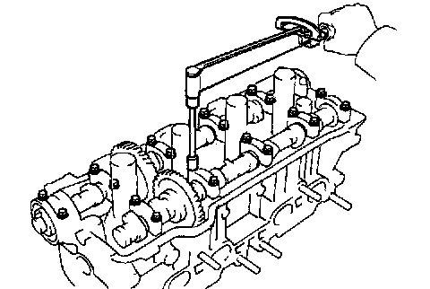
15. Inspect camshaft thrust clearance.
a. Install the camshaft.
b. Using a dial indicator, measure the thrust clearance while moving the camshaft back and forth.
Standard thrust clearance:
Intake: 0.045 - 0.100 mm (0.0018 - 0.0039 inch)
Exhaust: 0.030 - 0.085 mm (0.0012 - 0.0033 inch)
Maximum thrust clearance:
Intake: 0.12 mm (0.0047 inch)
Exhaust: 0.10 mm (0.0039 inch)
If the thrust clearance is greater than maximum, replace the camshaft. If necessary, replace the bearing caps and cylinder head as a set.

16. Inspect camshaft gear backlash.
a. Install the camshafts without installing the exhaust cam sub-gear.
b. Using a dial indicator, measure the backlash.
Standard backlash: 0.020 - 0.200 mm (0.0008 - 0.0079 inch)
Maximum backlash: 0.30 mm (0.0188 inch)
If the backlash is greater then maximum, replace the camshafts.
17. Inspect valve lifters and lifter bores.

a. Using a caliper gauge, measure the lifter bore diameter of the cylinder head.
Lifter bore diameter: 31.000 - 31.018 mm (1.2205 - 1.2212 inch)

b. Using a micrometer, measure the lifter diameter.
Lifter diameter: 30.966 - 30.976 mm (1.2191 - 1.2195 inch)
c. Subtract the lifter diameter measurement from the lifter bore diameter measurement.
Standard oil clearance: 0.024 - 0.052 mm (0.0009 - 0.0020 inch)
Maximum oil clearance: 0.07 mm (0.0028 inch)
If the oil clearance is greater than maximum, replace the lifter. If necessary, replace the cylinder head.

18. Inspect intake manifolds.
Using a precision straight edge and feeler gauge, measure the surface contacting the cylinder head for warpage.
Maximum warpage: 0.30 mm (0.0118 inch)
If warpage is greater than maximum, replace the manifold.

19. Inspect exhaust manifolds.
Using a precision straight edge and feeler gauge, measure the surface contacting the cylinder head for warpage.
Maximum warpage: 0.30 mm (0.0118 inch)
If warpage is greater than maximum, replace the manifold.
REPLACEMENT

1. Replace valve guide bushings.
a. Exhaust (w/ Snap Ring:)
Insert an old valve wrapped with tape into the valve guide bushing, and break off the valve guide bushing by hitting it with a hammer. Remove the snap ring.
HINT: Wrap the tape approximately 8 mm (0.31 inch) from the valve stem end.
NOTICE: Be careful not to damage the valve lifter hole.

b. Gradually heat the cylinder head to 80 - 100°C (173 - 212°F).

c. Using Special Service Tool (SST) 09201 - 10000 (09201 - 01060), 09950 - 70010 (09951 - 07100) or equivalent, and a hammer, tap out the guide bushing.

d. Using a caliper gauge, measure the bushing bore diameter of the cylinder head.

e. Select a new guide bushing (STD or O/S 0.05).
If the bushing bore diameter of the cylinder head is greater than 11.012 mm (0.4335 inch), machine the bushing bore to the following dimension:
11.035 - 11.062 mm (0.4344 - 0.4355 inch)
If the bushing bore diameter of the cylinder head is greater than 11.062 mm (0.4355 inch), replace the cylinder head.

HINT: Different the bushings are used for the intake and exhaust.
f. Gradually heat the cylinder heat to 80 - 100°C (176 - 212°F).

g. intake:
Using SST and a hammer, tap in a new guide bushing until there is 8.0 - 8.8 mm (0.315 - 0.346 inch) protruding from the cylinder head.
h. Exhaust:
Using SST and a hammer, tap in a new guide bushing until the snap ring makes contact with the cylinder head.

i. Using a sharp 6.0 mm (0.236 inch) reamer, ream the guide bushing to obtain the standard specified clearance between the guide bushing and valve stem.