Unit Repair
GENERAL DESCRIPTION
The A140E automatic transaxle described is a 4-speed lock-up automatic transaxle developed exclusively for use with a transversely-mounted engine.

General Specifications
OPERATION

Operation


Function of Components

Power from the engine transmitted to the input shaft via the torque converter is then transmitted to the planetary gears by the operation of the clutch. By operation of the brake and one-way clutch, either the planetary carrier or the planetary sun gear are immobilized, altering the speed of revolution of the planetary gear unit. Shift change is carried out by altering the combination of clutch and brake operation. Each clutch and brake operates by hydraulic pressure; gear position is decided according to the throttle opening angle and vehicle speed, and shift change automatically occurs. The conditions of operation for each gear position are shown in the illustrations.

Hydraulic Control System
The hydraulic control system is composed of the oil pump, the valve body, the solenoid valves, the accumulators, the clutches and brakes, and the governor valve as well as the fluid passages which connect all of these components. Based on the hydraulic pressure created by the oil pump, the hydraulic control system governs the hydraulic pressure acting on the Torque Converter Clutch (TCC), clutches and brakes in accordance with the vehicle driving conditions. There are three solenoid valves on the valve body. The No.1 and No.2 solenoid valves are turned on and off by signals from the Engine Control Module (ECM) to operate the shift valves and change the gear shift position. The No.3 solenoid valve is operated by signals from the ECM to engage or disengage the lock-up clutch of the torque converter.
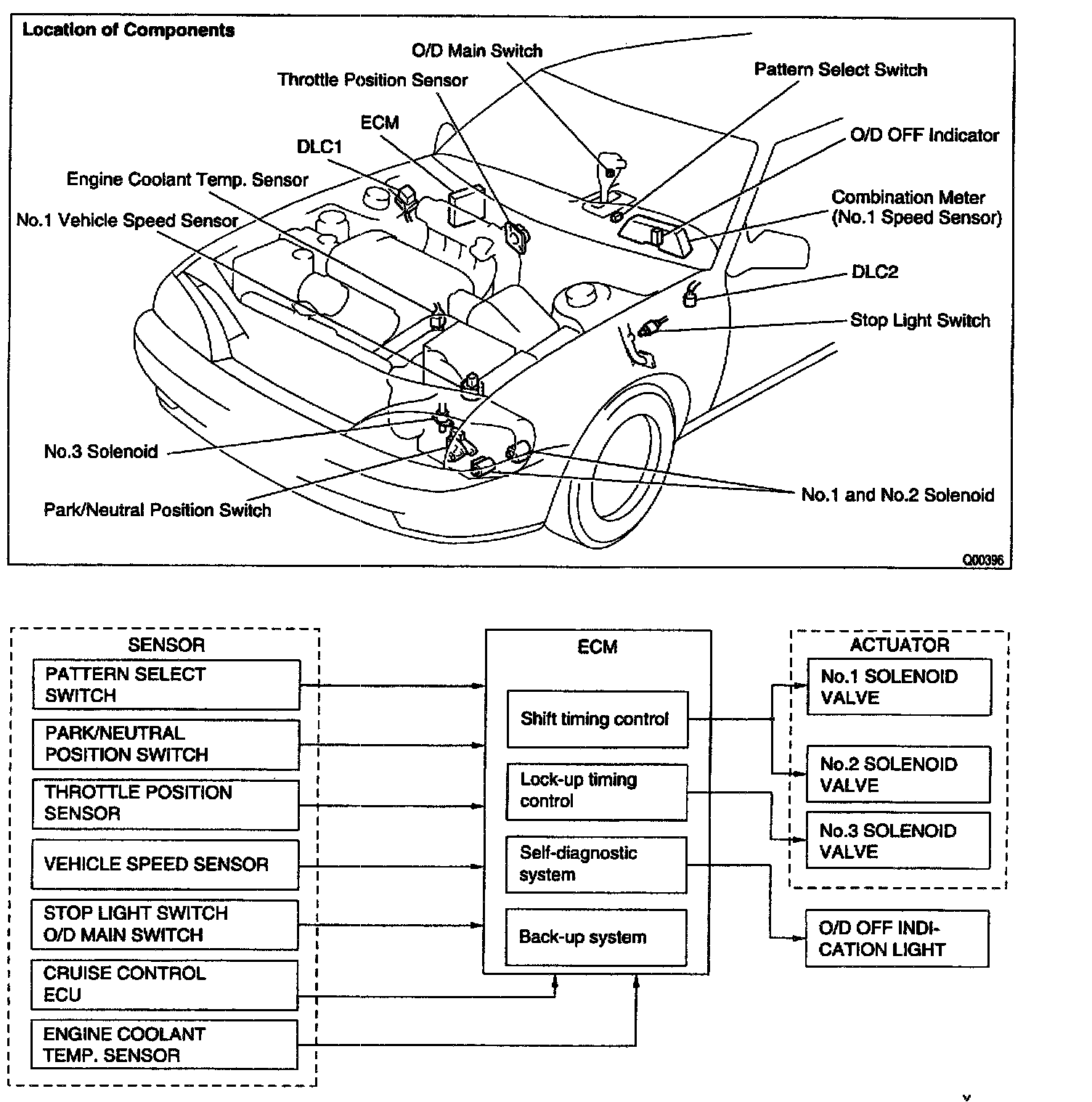
Electronic Control System
The electronic control system for controlling the shift timing and the operation of the lock-up clutch is composed of the following 3 parts:
a. Sensors: These sense the vehicle speed and throttle position and send this data to the ECM in the form of electronic signals.
b. ECM: This determines the shift and lock-up timing based upon the signals from the sensors.
c. Actuators: Solenoid valves divert hydraulic pressure from one circuit of the hydraulic control unit to another, thus controlling shifting and lock-up timing.