Part 1
COMPONENT PARTS INSTALLATIONComponent Parts Installation
Disassembly, inspection and assembly of each component group have been indicated in the preceding chapter. Before assembly, make sure, again, that all component groups are assembled correctly.
If something wrong is found in a certain component group during assembly, inspect and repair this group immediately.
Recommended Automatic Transaxle Fluid (ATF): DEXRON (R) II
General Installation Notes:
1. The automatic transaxle is composed of highly precision-finished parts, necessitating careful inspection before assembly because even a small nick could cause fluid leakage and affect performance.
2. Before assembling new clutch discs, soak them in ATF for at least 15 minutes.
3. Apply automatic transaxle fluid on the sliding or rotating surfaces of parts before assembly.
4. Use petroleum jelly to keep small parts in their places.
5. Do not use adhesive cements on gaskets and similar parts.
6. When assembling the transaxle, be sure to use new gaskets and O-rings.
7. Dry all parts with compressed air - never use shop rags.
8. Be sure to install the thrust bearings and races in the correct direction and position.

Bearing And Race Diameters
Drive Pinion Assembly Installation

1. INSTALL NEW O-RING ONTO BEARING CAGE
2. INSTALL DRIVE PINION SHAFT INTO CASE
Slightly tap the cage into the case until the groove with the bore can be seen.
HINT: Drive in the bearing cage until the surface of the bearing cage passes through the groove with the bore.
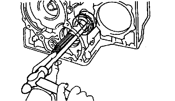
3. INSTALL SNAP RING INTO CASE

a. Using Special Service Tools (SST), install the snap ring into the groove.
SST 09350-32014 (09351-32050)
b. Slightly tap the drive pinion to fit the snap ring into the groove.

4. INSTALL ROTOR SENSOR
Install the rotor sensor, facing the magnet outward.

5. INSTALL OIL SLINGER
Install the oil slinger, facing the lip outward.

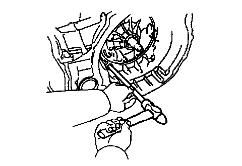
6. INSTALL OUTER RACE
Using SST, drive the outer race into the case.
SST 09350-32014 (09351-32100, 09351-32140)
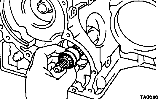
7. INSTALL NEW SPACER
Always use new spacer. Install the spacer with the small end first.
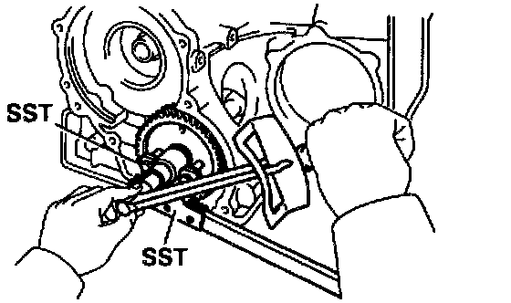
8. INSTALL COUNTER DRIVEN GEAR ONTO SHAFT

a. Place a bar at the drive pinion side and position the outer end of the bar against a vise or similar.
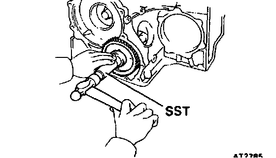
b. Using SST, driven in gear onto the shaft until the nut can be installed on the threads of the shaft.
NOTICE: Be careful not to cause an impact to the transaxle case.
SST 09350-32014 (09351-32140)
9. ADJUST DRIVE PINION PRELOAD
a. Coat the threads and surface of the nut with MP grease.
b. Using SST to hold the gear, tighten the nut.
Torque: 172 Nm (1,750 kgf.cm, 127 ft. lbs.)
SST 09330-00021, 09350-32014 (09351-32032)
c. Turn the gear counterclockwise and clockwise several times.

d. Using a torque meter, measure the preload of the drive pinion.
Preload (at starting):
New bearing: 1.0 - 1.6 Nm (10 - 16 kgf.cm, 8.7 - 13.9 inch lbs.)
Reused bearing: 0.5 - 0.8 Nm (5 - 8 kgf.cm, 4.3 - 6.9 inch lbs.)
- If the preload is greater than specified, replace the bearing spacer.
- If the preload is less than specified, retighten the nut 13 Nm (130 kgf.cm, 9 ft. lbs.) at a time until the specified preload is reached.
If the maximum torque is exceeded while retightening the nut, replace the bearing spacer and repeat the preload procedure. Do not back off the nut to reduce the preload.
Maximum torque: 289 Nm (2,950 kgf.cm, 213 ft. lbs.)
e. If the preload is adjusted within specification, make a note of it.
Differential Installation

1. PLACE OUTER RACE AND SELECTED ADJUSTING SHIM ONTO RH SIDE BEARING

2. PLACE DIFFERENTIAL CASE INTO CASE
Be sure to install the adjusting shim into place.

3. INSTALL LH BEARING RETAINER
a. Install a new 0-ring.
b. Position the retainer by tapping it while holding the differential case center with the retainer.
c. Clean the threads of the bolts and case with white gasoline.
d. Coat the threads of the bolts with sealer.
Sealer: Part No. 08833-00070, THREE BOND 1324 or equivalent

e. Temporarily tighten the bolts evenly and gradually while turning the ring gear.

4. INSTALL RH SIDE BEARING CAP
Tighten the bolts evenly and gradually while turning the ring gear.
Torque: 72 Nm (730 kgf.cm, 53 ft. lbs.)

5. TIGHTEN LH BEARING RETAINER
Torque: 19 Nm (195 kgf.cm, 14 ft. lbs.)

6. MEASURE TOTAL PRELOAD
Using a torque meter, measure the total preload of the drive pinion shaft.
Total preload (at starting):
Add drive pinion preload
New Bearing: 0.3 - 0.4 Nm (2.9 - 4.0 kgf.cm, 2.5 - 3.5 inch lbs.)
Reused bearing: 0.1 - 0.2 Nm (1.5 - 2.0 kgf.cm, 1.3 - 1.7 inch lbs.)
If the preload is not within specification, redisassemble and readjust.
7. STAKE COUNTER DRIVEN GEAR NUT
8. INSTALL DRIVE PINION CAP

9. INSTALL CARRIER COVER
a. Clean the threads of the bolts and case with white gasoline.
b. Coat the threads of the bolts with sealer.
Sealer: Part No. 08833-00070, THREE BOND 1324 or equivalent
c. Install the carrier cover over the gasket.
Torque: 25 Nm (250 kgf.cm, 18 ft. lbs.)
4-Speed Gear Unit Installation

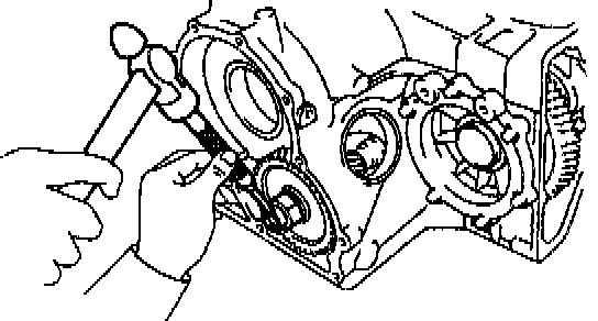
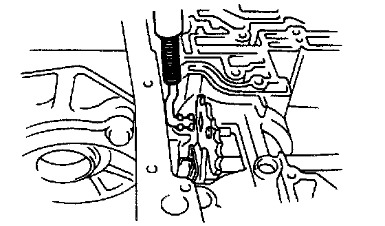
1. INSTALL MANUAL VALVE SHAFT
a. Coat the oil seal lip with MP grease.
b. Using a socket wrench and hammer, drive in a new manual valve shaft oil seal to the case.

c. Assemble a new collar to the manual valve lever.

d. Install the manual valve lever shaft to the transaxle case through the manual valve lever.
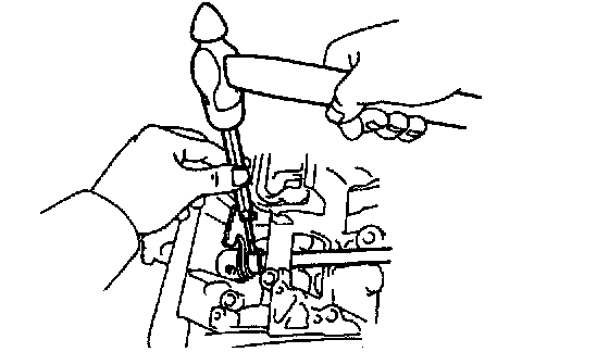
e. Using a pin punch, drive in the roll pin until its surface is flush with the manual valve lever surface.

f. Match the collar hole to the lever calking hollow and calk the collar to the lever.

g. Install the retaining spring.
h. Make sure that the lever moves smoothly.
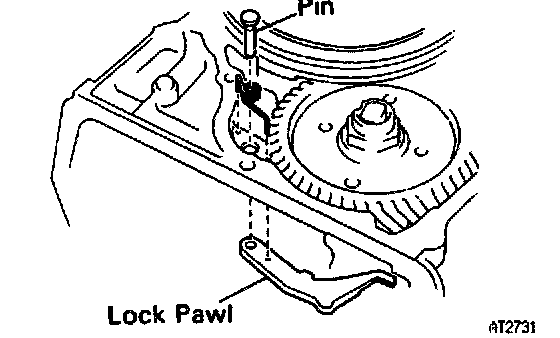
2. INSTALL PARKING LOCK PAWL
a. Place the parking lock pawl onto the case. Hook the spring ends to the case and pawl.
b. Install the pin into the hole of the case through the spring and pawl.
3. INSTALL PARKING LOCK ROD

4. INSTALL PARKING LOCK PAWL BRACKET
Torque: 7.4 Nm (75 kgf.cm, 65 inch lbs.)

5. CHECK OPERATION OF PARKING LOCK PAWL
Make sure the counter driven gear is locked when the manual valve lever is in the P position.
6. INSTALL FIRST AND REVERSE BRAKE PISTON TO TRANSMISSION CASE
a. Coat new O-rings with ATF.
b. Install the 2 O-rings on the piston.

c. Push the piston into the bore of the case, facing the spring seat upward.
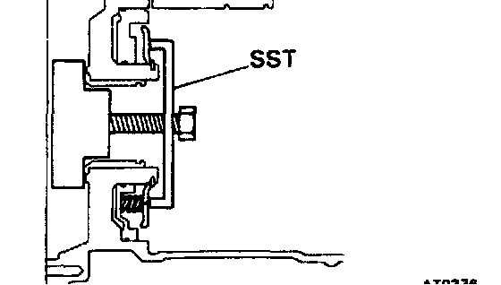
7. INSTALL PISTON RETURN SPRING
a. Place the return spring and snap ring on the piston.
b. Place Special Service Tools (SST), and compress the return spring evenly by tightening the bolt gradually.
SST 09350-32014 (09351-32040)
c. Install snap ring. Visually check to make sure it is fully seated and centered by the 3 lugs on the spring retainer. Be sure the end gap of snap ring is not aligned with the spring retainer claw.
d. Remove SST.
8. INSTALL OVERDRIVE UNIT

a. Install the overdrive brake apply gasket and overdrive clutch apply gasket.

b. Install the overdrive brake drum to the case.
c. Install a new case gasket to the case.

d. Make sure that the length from the top surface of the case to the counter driven gear top surface should be about 24 mm (0.94 inch).
e. Install the overdrive unit with overdrive case to the transaxle case.

f. Install and tighten the bolts.
Torque: 25 Nm (250 kgf.cm, 18 ft. lbs.)

9. CHECK INTERMEDIATE SHAFT END PLAY
a. Make sure that the intermediate shaft has thrust play.
Thrust play: 0.49 - 1.51 mm (0.0193 - 0.0594 inch)
If the thrust play is not within specification, check the installation of intermediate shaft.
b. Make sure that the intermediate shaft turns smoothly.

10. INSTALL FIRST AND REVERSE BRAKE IN CASE
a. Install the inner flange facing the flat end toward the oil pump side.
b. Install the discs and plates.
Install in order: P=Plate D=Disc
D - P - D - P - D - P - D - P - D - P - D
c. Install the outer flange, facing the flat end toward the piston side.
11. INSTALL SNAP RING
Be sure the end gap of the snap ring is not aligned with one of the cutouts.

12. CHECK OPERATION OF FIRST AND REVERSE BRAKE
Apply compressed air into the oil passage with the case and be sure that the piston moves.
13. INSTALL RING GEAR INTO CASE

a. Coat the races and bearing with petroleum jelly and install them onto the ring gear.

Bearing And Races

b. Install the ring gear into the case.
14. INSTALL REAR PLANETARY GEAR INTO CASE

a. Align the flukes of the discs in the first and reverse brake.
b. Coat the thrust washer with petroleum jelly. Align the tab of the washer with the hollow of the carrier.

c. Align the spline of the planetary carrier with either of the flukes of the discs, and install the planetary gear into the first and reverse brake discs.

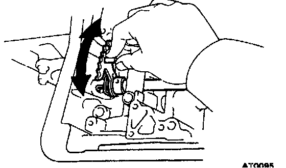
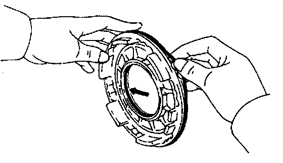
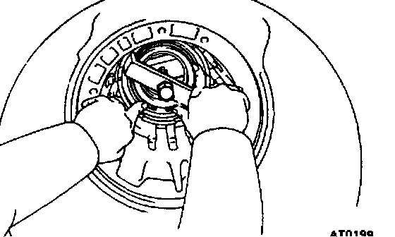
15. INSTALL NO.2 ONE-WAY CLUTCH INTO CASE WITH SHINY SIDE UPWARD
a. Place the one-way clutch with the shiny side upward.
b. Install the one-way clutch onto the inner race while turning the planetary gear clockwise with SST.
SST 09350-32014 (09351-32050)

c. Coat the thrust washer with petroleum jelly and install it onto the planetary gear.

16. CHECK OPERATION OF NO.2 ONE-WAY CLUTCH
Turn the planetary carrier. The carrier should turn freely clockwise and lock counterclockwise.
17. INSTALL SNAP RING
Be sure the end gap of the snap ring is not aligned with one of the cutouts.

18. INSTALL SECOND COAST BRAKE BAND GUIDE
Install the 2 band guides so that its tip touches the case.

19. INSTALL SECOND BRAKE INTO CASE
a. Install the flange, facing the flat end toward the oil pump side.
b. Install the discs and plates.
Install in order: P=Plate D=Disc
Flange - D - P - D - P - D - P

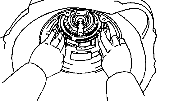
20. INSTALL PISTON RETURN SPRING
Each spring end is installed onto the protrusion with the case.

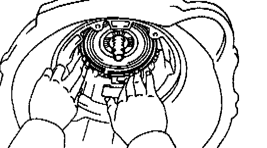
21. INSTALL SECOND BRAKE DRUM INTO CASE
Align the groove of the drum with the bolt and place it into the case.
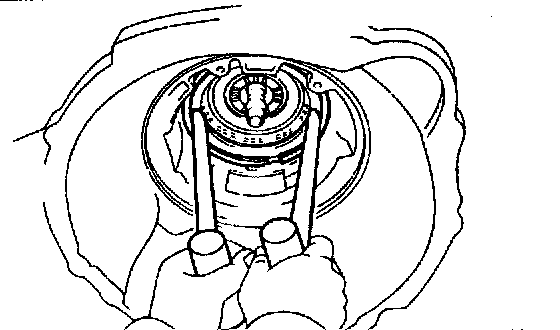
22. INSTALL SNAP RING
a. Place the snap ring into the case so that the end gap is installed into the groove.
b. While compressing the piston return springs over the drum with hammer handles, install the snap ring into the groove.
c. Be sure the end gap of the snap ring is not aligned with one of the cutouts.