Part 2

23. INSTALL SECOND BRAKE DRUM GASKET
Install a new gasket until it makes contact with the second brake drum.

24. CHECK OPERATION OF SECOND BRAKE
Blow compressed air into the oil passage with the case, and be sure that the piston moves.

25. INSTALL NO.1 ONE-WAY CLUTCH AND SECOND BRAKE HUB
a. Align the flukes of the discs in the second brake.
b. Align the spline of the hub with the flukes of the discs and install the hub to the second brake discs.

c. Check the distance between the surfaces of the second brake hub and rear planetary gear.
Distance: Approximately 5 mm (0.20 inch)

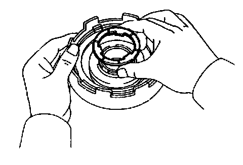
26. INSTALL SUN GEAR AND SUN GEAR INPUT DRUM
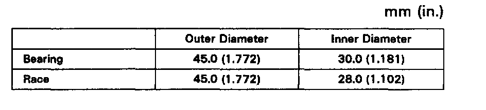
While turning the sun gear clockwise, install it into the one-way clutch.
27. INSTALL FRONT PLANETARY GEAR ONTO RING GEAR

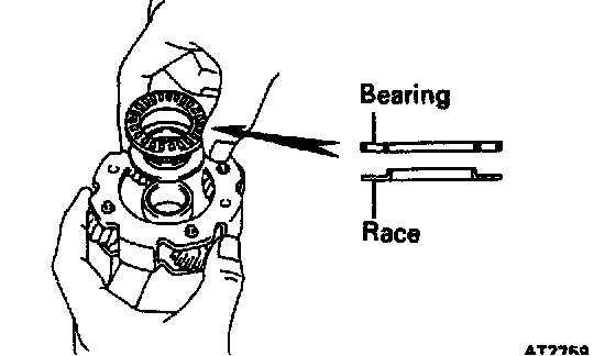
a. Coat the races and bearing with petroleum jelly, and install them onto the ring gear.

Bearing and race
b. Coat the race and bearing with petroleum jelly, and install them onto the planetary gear.
Bearing and race
c. Install the planetary gear onto the ring gear.
28. INSTALL FRONT PLANETARY GEAR ASSEMBLY ONTO SUN GEAR

a. If the planetary gear and other parts are installed correctly into the case, the end of the bushing with the ring gear flange will be flush with a shoulder of the intermediate shaft or under.
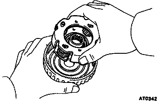
b. Coat the race with petroleum jelly and install it onto the tip of ring gear flange.

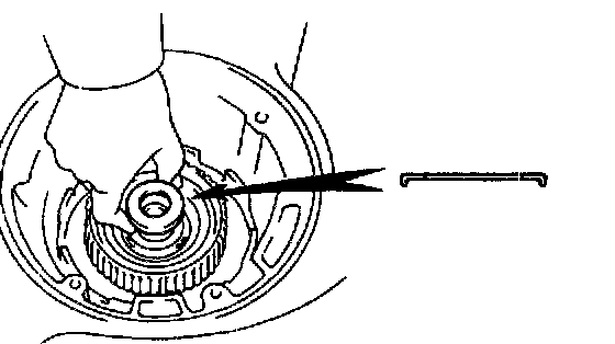
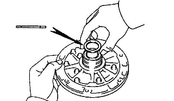
29. INSTALL INTERMEDIATE SHAFT OIL SEAL RING

30. INSTALL SECOND COAST BRAKE BAND
a. Place the band into the case.
b. Install the pin through the oil pump mounting bolt hole.
31. INSTALL FORWARD CLUTCH AND DIRECT CLUTCH


a. Coat the races and bearing with petroleum jelly, and install them onto both sides of the clutch drum.

Bearing and race (Front side)

Bearing and race (Rear side)
b. Coat the clutch drum thrust washer with petroleum jelly and install it with the oil groove facing upward onto the direct clutch drum.

c. Align the flukes of discs in the direct clutch.

d. Mesh the hub with the flukes of the direct clutch while turning the clutch drum or forward clutch.
e. If the flukes of the discs are meshed with the hub correctly, the end of the bushing with the direct clutch drum will be flush with the surface of the forward clutch.

f. Place the direct clutch and forward clutch into the case.
g. Rotate the forward clutch to mesh the front planetary ring gear and discs.

h. Check the distance between the A and B.
Distance: Approximately 3 mm (0.118 inch)
32. INSTALL OIL PUMP INTO CASE
a. Coat the race with petroleum jelly and install it onto stator shaft.

b. Coat a new O-ring with ATF and install it to oil pump.
c. Place the oil pump through the input shaft, and align the bolt holes of the pump body with the transaxle case.

d. Hold the input shaft, and lightly press the oil pump body to slide the oil seal rings on the stator shaft through the direct clutch drum.
NOTICE: Do not push on the oil pump strongly or the oil seal ring will stick to the direct clutch drum.

e. Install and tighten the 7 bolts.
Torque: 22 Nm (225 kgf.cm, 16 ft. lbs.)
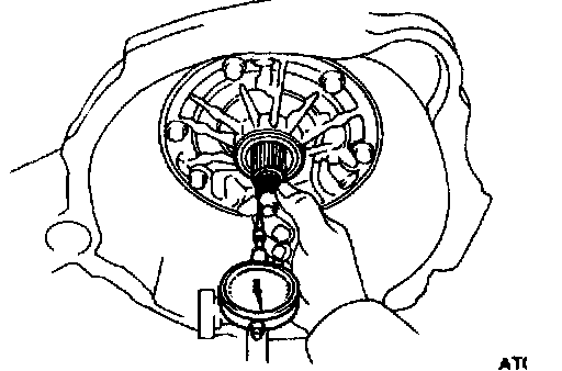
33. MEASURE THRUST PLAY OF INPUT SHAFT
Measure the thrust play with a dial gauge.
Thrust play: 0.3 - 0.9 mm (0.012 - 0.035 inch)
HINT: There are 2 thickness of races for the end of stator shaft. If the thrust play is in excess of standard, select one of them.
Race thicknesses:
0.8 mm (0.031 inch)
1.4 mm (0.055 inch)

34. CHECK INPUT SHAFT ROTATION
Make sure that the input shaft rotates smoothly.

35. INSTALL DRIVE PINION CAP

36. INSTALL SECOND COAST BRAKE PISTON
a. Coat new O-rings with ATF and install them on the cover.
b. Install the outer spring with the piston.
c. Place the cover into the bore.

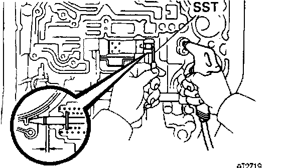
d. Using SST, install the snap ring while pressing the cover.
SST 09350-32014 (09351-32050)
e. Check that the front end of the piston rod contacts the center of the second brake band depression.
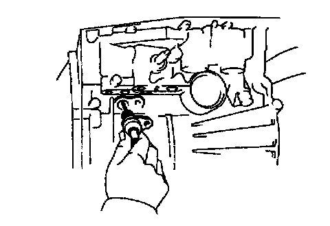
37. CHECK SECOND COAST BRAKE PISTON STROKE
a. Apply a small amount of paint to the piston rod at the point it meets the case.
b. Using SST, measure the piston stroke while applying and releasing compressed air (392 - 785 kPa, 4 - 8 kgf.cm, 57 - 114 psi).
SST 09240-00020
Piston stroke: 1.5 - 3.0 mm (0.059 - 0.118 inch)
If the stroke is more than standard value, replace the piston rod with a longer one.
Piston rod length:
72.9 mm (2.870 inch)
71.4 mm (2.811 inch)
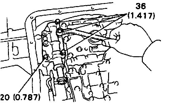
38. INSTALL ACCUMULATOR PISTONS AND SPRINGS


a. Install the springs and pistons into the bore.

b. Place the cover with the gasket and tighten the bolts gradually in sequence.
HINT: Each bolt length (mm, inch) is indicated in the illustration.

39. INSTALL NEW SECOND BRAKE APPLY GASKET

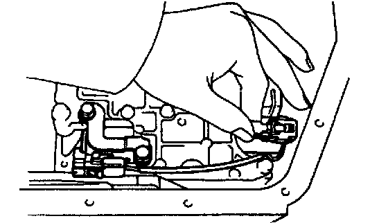
40. INSTALL THROTTLE CABLE IN CASE
Push the cable through the case, being careful not to damage the O-ring. Check for full seating.
NOTICE: In subsequent work, to avoid breaking the cable fitting do not roll the case over the cable.
41. INSTALL SOLENOID WIRING

42. PLACE VALVE BODY ON TRANSAXLE
a. While holding the cam down by your hand, slip the cable end into the slot.
b. Lower the valve body into place.
NOTICE: Do not entangle the kick-down switch wire or solenoid wire.

43. INSTALL BOLTS IN VALVE BODY
HINT: Each bolt length (mm, inch) is indicated in the illustration. Hand tighten the 12 bolts first, then torque with a torque wrench.
Torque: 10 Nm (100 kgf.cm, 7 ft. lbs.)
44. INSTALL MANUAL VALVE BODY AND DETENT SPRING
HINT: Each bolt length (mm, inch) is indicated in the illustration.
a. Align the manual valve with the pin on the manual shaft lever.
b. Lower the manual valve body into place.
c. Hand tighten the 4 bolts first. Then, tighten them with a torque wrench.
Torque: 10 Nm (100 kgf.cm, 7 ft. lbs.)

d. Place the detent spring on the manual valve body and hand tighten the 2 bolts first. Then, tighten them with a torque wrench.
Torque: 10 Nm (100 kgf.cm, 7 ft. lbs.)
e. Check that the manual valve lever is touching the center of the detent spring tip roller.

45. INSTALL OIL TUBES
Using a plastic hammer, install the 4 tubes into the positions indicated in the illustration.
NOTICE: Be careful not to bond or damage the tubes.

46. INSTALL TUBE BRACKET
Torque: 10 Nm (100 kgf.cm, 7 ft. lbs.)

47. INSTALL OIL STRAINER
Each bolt length (mm, inch) is indicated in the figure.
Torque: 10 Nm (100 kgf.cm, 7 ft. lbs.)
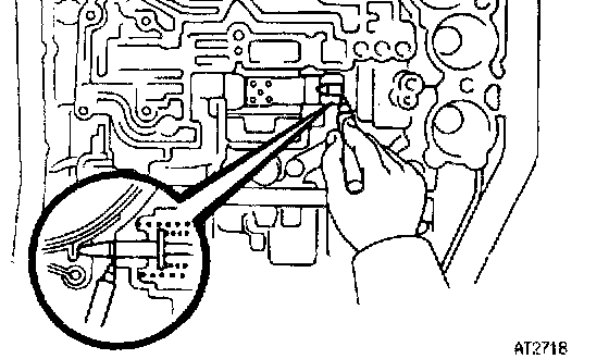
48. CONNECT SOLENOID WIRING
a. Connect the No.1 solenoid connector. (white and shorter wire)
b. Connect the No.2 solenoid connector. (black and longer wire)

49. INSTALL 3 MAGNETS IN PLACE
NOTICE: Make sure that the magnets do not interfere with the oil tubes.

50. INSTALL OIL PAN WITH NEW GASKET
Torque: 4.9 Nm (50 kgf.cm, 43 inch lbs.)

51. INSTALL COVER

52. INSTALL COVER BRACKET

53. INSTALL SOLENOID WIRING RETAINING PLATE
54. INSTALL THROTTLE CABLE RETAINING PLATE
55. INSTALL FILLER TUBE AND BRACKET

56. INSTALL SL SOLENOID
a. Coat the O-ring with ATF and push the tip of the SL solenoid into the hole.
b. Tighten the 2 bolts evenly and gradually.

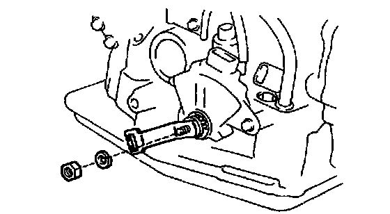
57. INSTALL PARK/NEUTRAL POSITION (PNP) SWITCH
a. Install the PNP switch to the manual valve shaft.
b. Install the seal gasket and locking plate.
c. Tighten the nut and stake it with the locking plate.
Torque: 6.9 Nm (70 kgf.cm, 61 inch lbs.)
58. ADJUST PNP SWITCH
a. Align the groove and return neutral basic line.
b. Lock the switch with 2 bolts.
Torque: 5.4 Nm (55 kgf.cm, 48 inch lbs.)

59. INSTALL UNION AND ELBOW
a. Coat new O-rings with ATF.
b. Install the O-rings to the union and elbow.
c. Install the union and elbow to the transaxle case.
Torque: 27 Nm (275 kgf.cm, 20 ft. lbs.)

HINT: Install the elbow as shown in the illustration.
60. INSTALL MANUAL SHIFT LEVER