Forward Clutch
FORWARD CLUTCH
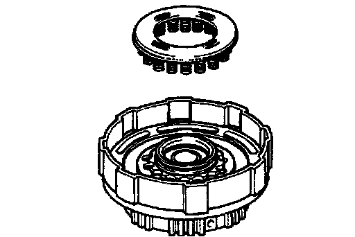
Components
Forward Clutch Disassembly


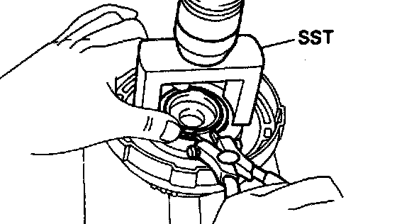
1. CHECK PISTON STROKE OF FORWARD CLUTCH
Set a dial indicator and measuring terminal (Special Service Tools) (SST) together, measure the forward clutch piston stroke while applying and releasing compressed air (392 - 785 kPa, 4 - 8 kgf/cm2, 57 - 114 psi).
SST 09350-32014 (09351-32190)
Piston stroke: 1.41 - 1.82 mm (0.0555 - 0.0717 inch)
If the piston stroke is greater than the maximum, inspect each component.

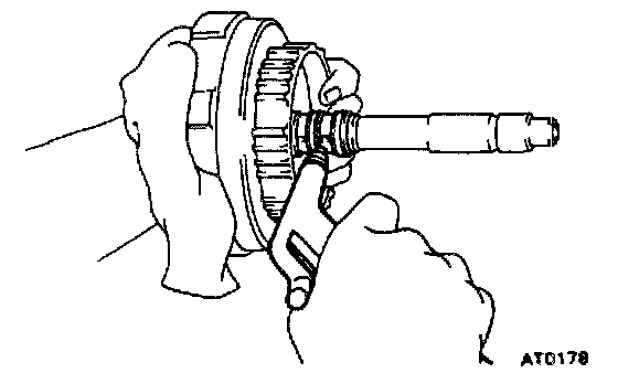
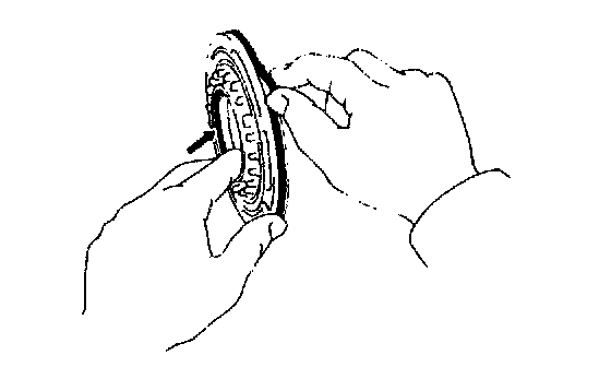
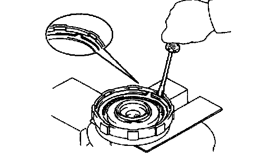
2. REMOVE SNAP RING FROM CLUTCH DRUM

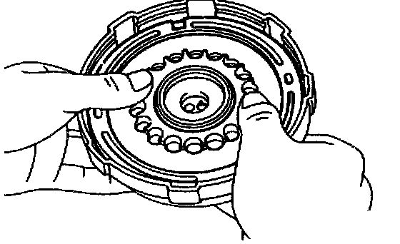
3. REMOVE FLANGE, DISCS AND PLATES
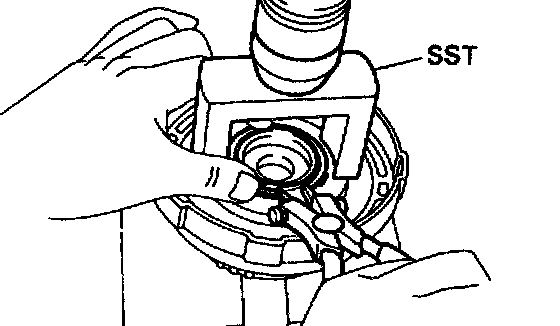
4. REMOVE RETURN SPRINGS
a. Place SST on the spring retainer and compress the springs with a shop press.
SST 09350-32014 (09351-32070)
b. Remove the snap ring with the snap ring pliers.
c. Remove the piston return spring.
5. REMOVE CLUTCH PISTON
a. Apply compressed air into the oil passage to remove the piston. If the piston does not come out, use needle-nose pliers to remove it.
b. Remove the 2 O-rings from the piston.

6. IF NECESSARY, REMOVE OIL SEAL RINGS
Remove the 2 oil seal rings from the shaft.
Forward Clutch Inspection

1. INSPECT CLUTCH PISTON
a. Check that the check ball is free by shaking the piston.
b. Check that the valve does not leak by applying low pressure compressed air.
2. INSPECT DISCS, PLATES AND FLANGE
Check if the sliding surfaces of the discs, plates and flange are worn or burnt. If necessary, replace them.
HINT:
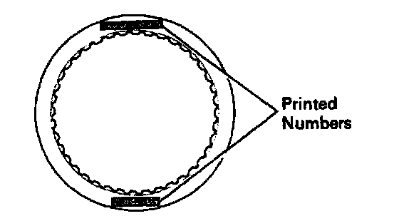
- If the lining of the disc is peeling off or discolored, or even if a part of the printed numbers are defaced, replace all discs.
- Before assembling new discs, soak them in Automatic Transmission Fluid (ATF) for at least 15 minutes.
Forward Clutch Assembly

1. INSTALL OIL SEAL RINGS
Install the 2 oil seal rings to the shaft.
NOTICE: Do not spread the ring ends more than necessary.
HINT: After installing the oil seal rings, check that they move smoothly.
2. INSTALL CLUTCH PISTON TO CLUTCH DRUM
a. Install the 2 new O-rings to the piston.
b. Coat the O-rings with Automatic Transmission Fluid (ATF).
c. Press the piston into the drum with the cup side up, being careful not to damage the O-rings.
3. INSTALL PISTON RETURN SPRINGS
a. Place the piston return spring and snap ring onto the piston.
b. Place Special Service Tools (SST) on the piston return spring, and compress the springs with a shop press.
SST 09350-32014 (09351-32070)
c. Install the snap ring with snap ring pliers. Be sure the end gap of the snap ring is not aligned with the spring retainer claw.

4. INSTALL PLATES, DISCS AND FLANGE
a. Install the plates and discs.
Install in order: P=Plate D=Disc
P - D - P - D - P - D - P - D
b. Install the flange with the flat end facing downward.
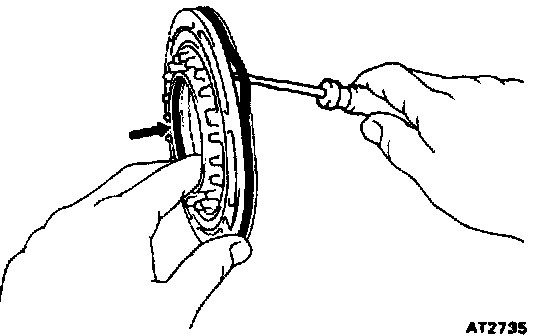
5. INSTALL SNAP RING
Check that the end gap of the snap ring is not aligned with one of the cutouts.

6. RECHECK PISTON STROKE OF FORWARD CLUTCH
Set a dial indicator and measuring terminal (SST) together, measure the forward clutch piston stroke while applying and releasing compressed air (392 - 785 kPa, 4 - 8 kgf/cm2, 57 - 114 psi).
SST 09350-32014 (09351-32190)
Piston stroke: 1.41 - 1.82 mm (0.0555 - 0.0717 inch)
If the piston stroke is less than the limit, parts may be disassembled and reinstall them. If the piston stroke is non-standard, select another flange.
HINT: There are 5 different flange thickness.
Flange thickness:
2.8 mm (0.110 inch)
3.0 mm (0.118 inch)
3.2 mm (0.126 inch)
3.4 mm (0.134 inch)
3.6 mm (0.142 inch)