Overhaul
DISASSEMBLY

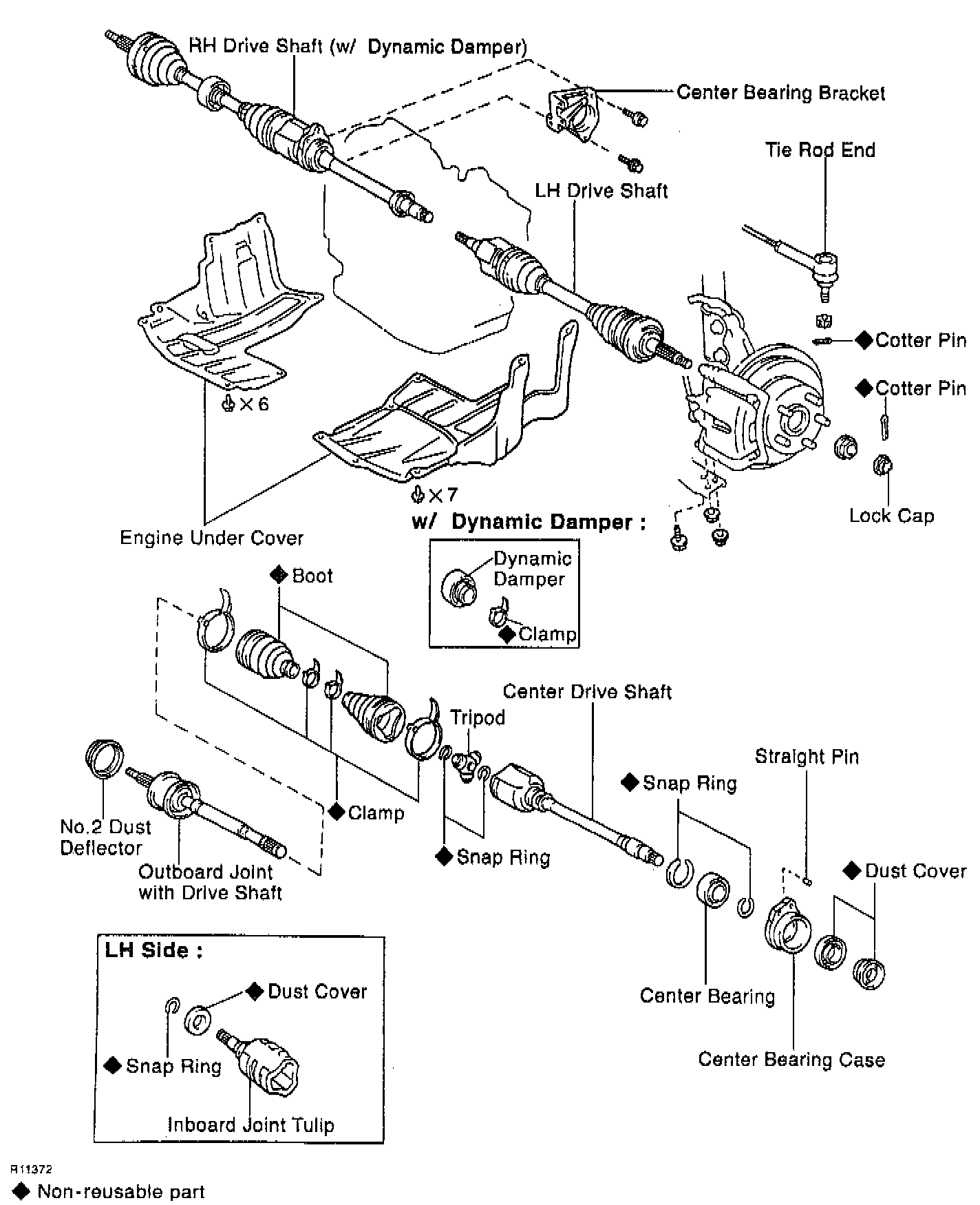
1. Check drive shaft.
a. Check to see that there is no play in the outboard joint.
b. Check to see that the inboard joint slides smoothly in the thrust direction.
c. Check to see that there is not noticeable play in the radial direction of the inboard joint.
d. Check for damage to boots.
2. Remove the inboard joint boot clamps.
a. Using a screwdriver, remove the two boot clamps.
b. Slide the inboard joint boot toward the outboard joint.
3. Disassemble the inboard joint tulip.

a. Place matchmarks on the tripod and inboard joint tulip or center drive shaft.
NOTICE: Do not punch the marks.
b. Remove the inboard joint tulip or center drive shaft from the drive shaft.
4. Remove the tripod.
a. Using a snap ring expander remove the snap ring.
b. Using a snap ring expander, temporarily slide the-snap ring toward the outboard joint side.

c. Place matchmarks on the drive shaft and tripod.
NOTICE: Do not punch the marks.
d. Using a brass bar and hammer, remove the tripod from the drive shaft.
NOTICE: Do not tap the roller.
e. Using a snap ring expander, remove the snap ring.
5. Remove the inboard joint boot.
6. M/T:
Remove dynamic damper.
a. Using a screwdriver, remove the clamp of the dynamic damper.
b. Remove the dynamic damper.
7. Remove the outboard joint boot.
a. Using a screwdriver, remove the two clamps of the outboard joint boot.
b. Remove the boot from the outboard joint.
NOTICE: Do not disassemble the outboard joint.

8. LH drive shaft.
Remove dust cover.
Using Special Service Tool (SST) 09950 - 00020 or equivalent, and a press, remove the dust cover from the inboard joint tulip.

9. RH drive shaft:
Remove dust cover.
Using a press, remove the dust cover from the center drive shaft.
10. RH drive shaft.
Disassemble center drive shaft.
a. Using a screwdriver, remove the snap ring.

b. Using a press, remove the bearing case.

c. Using SST 09950 - 00020 and a press, remove the dust cover.
d. Using a snap ring expander, remove the snap ring.

e. Using a press, remove the bearing.
f. Using a snap ring expander, remove the snap ring.
g. Using a pin punch and hammer, remove the straight pin.
11. Remove the No.2 dust deflector.
a. Mount the outboard joint shaft in a soft jaw vise.
b. Using a screwdriver and hammer, remove the No.2 dust deflector.
NOTICE: Be careful not to damage the ABS speed sensor.
ASSEMBLY

1. Install new No.2 dust deflector.
Using SST 09309 - 36010, 09316 - 20011 and a press, install a new No.2 dust deflector.
NOTICE: Be careful not to damage the ABS speed sensor.
2. RH drive shaft:
Assemble the center drive shaft.

a. Using a pin punch and hammer, install the straight pin into the bearing case.

b. Using SST 09950 - 60010 (09951 - 00640), 09950 - 70010 (09951 -07150) and a press, install a new bearing into the bearing case.
c. Using a screwdriver, install a new snap ring.

d. Using SST 09710 - 30021 (09710 - 03141) and a press, install a new bearing into the bearing case assembly to the center drive shaft.
e. Using a snap ring expander, install a new snap ring.

f. Using SST 09506 - 35010, a steel plate and press, install a new dust cover.
HINT: The clearance between the dust cover and the bearing should be kept in the ranges shown in the illustration.

3. LH drive shaft.
Install the dust cover.
Using a press, install a new dust cover.

4. RH drive shaft.
Using a steel plate and press, install a new dust cover until the distance from the tip of the center drive shaft. to the dust cover reaches the specification, as shown in the illustration.

5. Temporarily install the boots and damper (M/T).
HINT: Before installing the outboard joint boot, wrap vinyl tape around the spline of the drive shaft to prevent damaging the two boots and damper.
a. Temporarily install a new outboard boot to the drive shaft.
b. M/T:
Temporarily install the dynamic damper to the drive shaft.

c. Temporarily install a new inboard joint boot to the drive shaft.
6. Install the tripod.
a. Using a snap ring expander, install a new snap ring.
b. Place the beveled side of the tripod axial spline toward the outboard joint.
c. Align the matchmarks placed before removal.
d. Using a brass bar and hammer, install the tripod to the drive shaft.
NOTICE: Do not tap the roller.
e. Using a snap ring expander, install a new snap ring.
7. Install boot to outboard joint.
Before assembling the boot, pack the outboard joint and boot with grease in the boot kit, then install the boot to outboard joint.
8. Install the inboard joint tulip to front drive shaft.
a. Pack the boot and inboard joint tulip with grease in the boot kit.
b. Align the matchmarks placed before removal, and install the inboard joint tulip to the drive shaft.
c. Temporarily install the boot to the inboard joint tulip.

9. Assemble the boot clamps to both boots.
a. Make sure the two boots are on the shaft groove.
b. Make sure that the two boots are not stretched or contracted when the drive shaft. is at standard length. The standard lengths are as follows.
Manual Transaxle:
- Right Side: 857.5 ± 5.0 mm (33.760 ± 0.197 inch).
- Left Side: 572.4 ± 5.0 mm (22.535 ± 0.197 inch).
Automatic Transaxle:
- Right Side: 862.0 ± 5.0 mm (33.937 ± 0.197 inch).
- Left Side: 576.9 ± 5.0 mm (22.713 ± 0.197 inch).
c. Place four new boot clamps to the two boots.
d. Using a screwdriver, bend the band and lock it.
10. M/T:
Assemble damper clamp.
a. Be sure the damper is on the shaft groove.

b. Set the distance within the specification, as shown.
Distance: 200.0 ± 5.0 mm (7.874 ± 0.197 inch).
c. Place a new damper clamp to the damper.
d. Using a screwdriver, bend the band and lock.