Part 2

OUTPUT SHAFT
Disassembly
1. INSPECT 1ST AND 2ND GEARS THRUST CLEARANCE
Using a feeler gauge, measure the thrust clearance.
Standard clearance:
1st gear: 0.10 - 0.29 mm (0.0039 - 0.0114 inch)
2nd gear: 0.20 - 0.44 mm (0.0079 - 0.0173 inch)
Maximum clearance:
1st gear: 0.35 mm (0.0138 inch)
2nd gear: 0.50 mm (0.0197 inch)
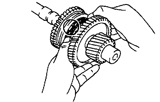
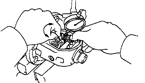
2. INSPECT 1ST AND 2ND GEARS RADIAL CLEARANCE
Using a dial indicator, measure the radial clearance between the gear and shaft. Ask
Standard clearance: 0.009 - 0.053 mm (0.0004 - 0.0021 inch)
Maximum clearance: 0.070 mm (0.0028 inch)
If the clearance exceeds the maximum, replace the gear, needle roller bearing or shaft.

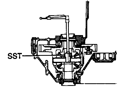
3. REMOVE REAR BALL BEARING, 4TH DRIVEN GEAR AND OUTPUT GEAR SPACER
a. Using SST and a press, remove the rear ball bearing and 4th driven gear.
SST 09950-00020
b. Remove the output gear spacer and ball.
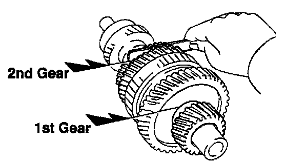
4. REMOVE 3RD DRIVEN GEAR, 2ND GEAR, NEEDLE ROLLER BEARING AND SYNCHRONIZER RING
a. Shift the No. 1 hub sleeve into the 1st gear.
b. Using SST and a press, remove the 3rd driven gear and 2nd gear.
SST 09950-00020
c. Remove the needle roller bearing and synchronizer rings.

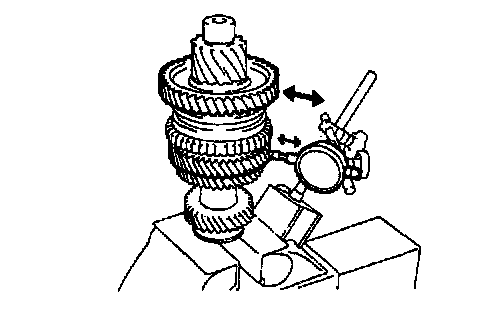
5. REMOVE NO.1 HUB SLEEVE ASSEMBLY, 1ST GEAR, SYNCHRONIZER RING, NEEDLE ROLLER BEARING, THRUST WASHER AND LOCKING BALL
a. Using a press, remove the No. 1 hub sleeve, 1st gear and synchronizer ring.
b. Remove the needle roller bearing and locking ball.
c. Using a screwdriver and hammer, drive out the thrust washer.

6. REMOVE NO.1 HUB SLEEVE, 3 SHIFTING KEYS AND SPRINGS FROM NO.1 CLUTCH HUB
Inspection

1. INSPECT 1ST GEAR SYNCHRONIZER RING
a. Check for wear or damage.
b. Check the braking of the synchronizer ring. Turn the synchronizer ring in one direction while pushing it to the gear cone. Check that the ring locks.
If the braking effect is insufficient, apply a small amount of the fine lapping compound between the synchronizer ring and gear cone. Lightly rub the synchronizer ring and gear cone together.
NOTICE: Ensure the fine lapping compound is completely washed off after rubbing.
c. Check again the braking effect of the synchronizer ring.

d. Using a feeler gauge, measure the clearance between the synchronizer ring back and the gear spline end.
Minimum clearance: 0.6 mm (0.024 inch)
If the clearance is less than the minimum, replace the synchronizer ring, and apply a small amount of the fine lapping compound on gear cone.
NOTICE: Ensure the fine lapping compound is completely washed off after rubbing.
2. INSPECT 2ND GEAR SYNCHRONIZER RING

a. Check for wear or damage.
b. Check the braking effect of the synchronizer ring. Turn the synchronizer ring in one direction while pushing it to the gear cone. Check that the ring locks.
If the braking effect is insufficient, replace the synchronizer ring.

c. Using a feeler gauge, measure the clearance between the synchronizer ring back and gear spline end.
Minimum clearance: 0.7 mm (0.028 inch)
If the clearance is less than the minimum, replace the synchronizer ring.

3. INSPECT SHIFT FORK AND HUB SLEEVE CLEARANCE
Using a feeler gauge, measure the clearance between the hub sleeve and shift fork.
Maximum clearance: 1.0 mm (0.039 inch)
If the clearance exceeds the maximum, replace the shift fork or hub sleeve.
4. INSPECT OUTPUT SHAFT
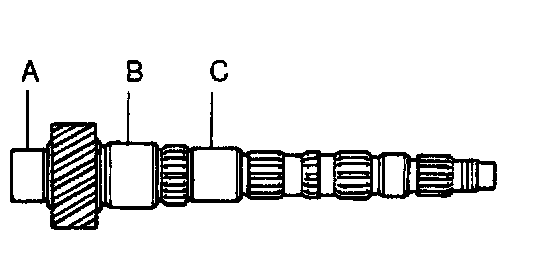
a. Using a micrometer, measure the outer diameter of the output shaft journal surface.
Minimum outer diameter:
Part A: 31.970 mm (1.2587 inch)
Part B: 37.970 mm (1.4949 inch)
Part C: 31.990 mm (1.2594 inch)
If the outer diameter is less than the minimum, replace the output shaft.

b. Using a dial indicator, check the shaft runout.
Maximum runout: 0.05 mm (0.0020 inch)
If the runout exceeds the maximum, replace the output shaft.
Reassembly
HINT: Coat all of the sliding and rotating surfaces with gear oil before reassembly.

1. INSTALL NO.1 CLUTCH HUB INTO HUB SLEEVE
a. Install the 3 springs and shifting keys to the clutch hub.
b. Install the hub sleeve to the clutch hub.
HINT: Position the identification groove of the hub sleeve to the front of the transmission.
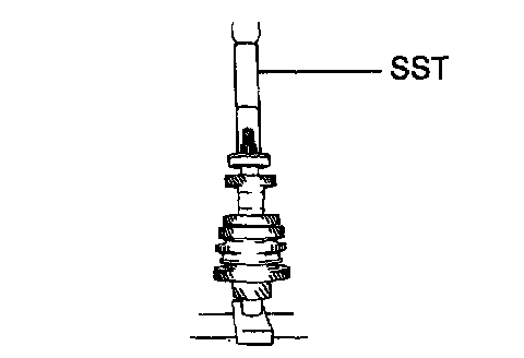
2. INSTALL THRUST WASHER, 1ST GEAR, NEEDLE ROLLER BEARING, SYNCHRONIZER RING AND NO.1 HUB SLEEVE TO OUTPUT SHAFT

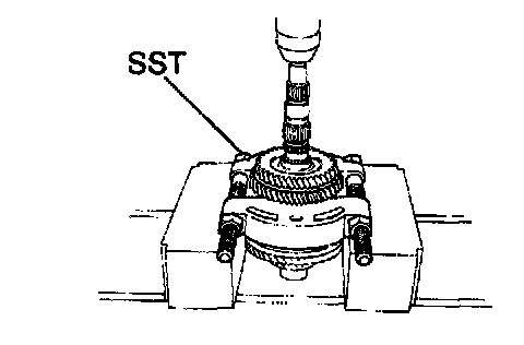
a. Using Special Service Tool (SST) and a press, install the thrust washer.
SST 09316-60011 (09316-00041)
b. Apply gear oil to the needle roller bearing.
c. Place the synchronizer ring on the gear and align the ring slots with the shifting keys.

d. Using a press, install the 1st gear and No-1 hub sleeve.
3. INSPECT 1ST GEAR THRUST CLEARANCE
4. INSTALL SYNCHRONIZER RING, 2ND GEAR, NEEDLE ROLLER BEARING AND 3RD DRIVEN GEAR

a. Install the ball.
b. Fit the 2nd gear bushing groove securely over the ball when installing the 2nd gear bushing on the shaft.
c. Place the synchronizer rings on the 2nd gear.
d. Apply gear oil to the needle roller bearing and install it.
e. Install the 2nd gear.
NOTICE: Align the clutch hub grooves with the projections on the synchronizer ring.

f. Using SST and a press, install the 3rd driven gear.
SST 09316-60011 (09316-00011)
5. INSPECT 2ND GEAR THRUST CLEARANCE

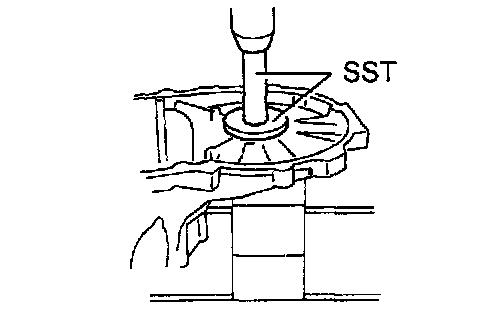
6. INSTALL OUTPUT GEAR SPACER, 4TH DRIVEN GEAR AND RADIAL BALL BEARING
a. Install the outer gear spacer.
b. Using a press, install the 4th driven gear and bearing.
7. INSTALL REAR BEARING
Using SST and a press, install the rear bearing.
SST 09612-22011
SHIFT AND SELECT LEVER SHAFT
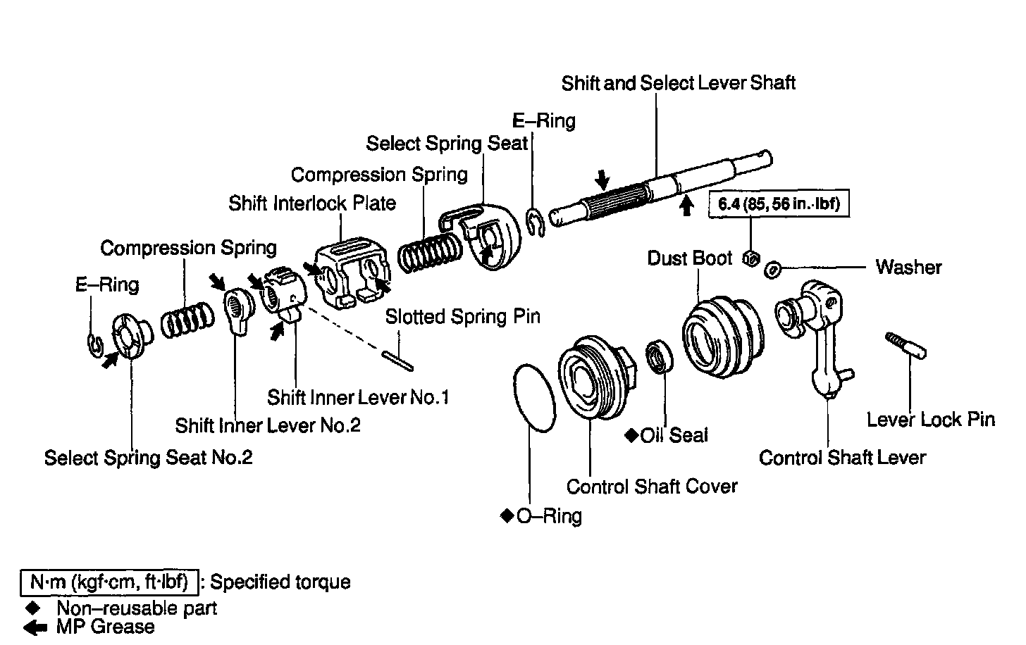
Components

DIFFERENTIAL CASE
Disassembly
1. Vehicle Speed Sensor Drive Gear Side: REMOVE SIDE BEARING FROM DIFFERENTIAL CASE
a. Using Special Service Tool (SST), remove the bearing from the drive gear side of the case.
SST 09950-00020,09950-00030
b. Remove the vehicle speed sensor drive gear.
2. REMOVE RING GEAR
a. Place matchmarks on the ring gear and case.
b. Remove the 8 bolts.
c. Using a copper hammer, tap on the ring gear to remove it from the case.

3. Ring Gear Side: REMOVE SIDE BEARING FROM DIFFERENTIAL CASE
Using SST, remove the bearing from the ring gear side of the case.
SST 09950-00020,09950-00030
4. INSPECT SIDE GEAR BACKLASH
Using a dial indicator, measure the backlash of one side gear while holding one pinion toward the case.
Standard backlash: 0.05 - 0.20 mm (0.0020 - 0.0079 inch)
If the backlash is not within the specification, install the correct thrust washer to the side gears.
5. DISASSEMBLE DIFFERENTIAL CASE
a. Using a pin punch and hammer, drive out the straight pin.
b. Remove the pinion shaft from the case.
c. Remove the 2 pinions and side gears with the 4 thrust washers from each gear.
6. Transaxle Case Side: IF NECESSARY, REPLACE DIFFERENTIAL SIDE BEARING RETAINER OIL SEAL

a. Using SST and a hammer, drive out the oil seal from the retainer.
SST 09950-60020 (09951-00680), 09950-70010 (09951-07150)

b. Using SST and a hammer, drive in a new oil seal until its surface is flush with the case surface.
SST 09350-32014 (09351-32130, 09351-32150)
c. Coat the lip of the oil seal with Multipurpose (MP) grease.

7. Transmission Case Side: IF NECESSARY, REPLACE SIDE OIL SEAL
a. Using a screwdriver and hammer, drive out the oil seal.
b. Using SST and a hammer, drive in a new oil seal until its surface is flush with the case surface.
SST 09350-32014 (09351-32130, 09351-32150)
c. Coat the lip of the oil seal with MP grease.
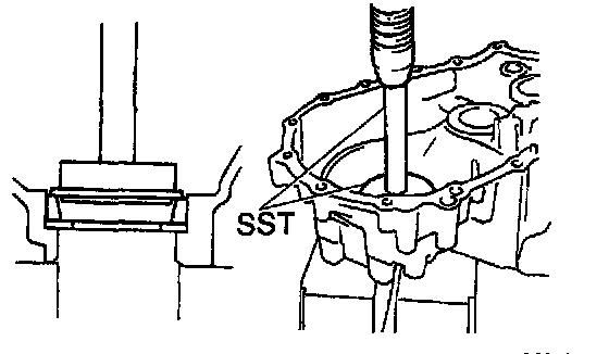
8. Transaxle Case Side: IF NECESSARY, REPLACE SIDE BEARING OUTER RACE

a. Using a brass bar and hammer, drive out the bearing outer race.
b. Install the bearing retainer without an O-ring.
c. Install and torque the 6 bolts.
Torque: 18 Nm (185 kgf-cm, 13 ft. lbs.)
d. Place the thinnest shim into the case.
e. Using SST and a press, install a new bearing outer race.
SST 09950-60020 (09951-00680), 09950-70010 (09951-07150)
f. Remove the 6 bolts.
g. Remove the bearing retainer and shim.
9. Transaxle Case Side: IF NECESSARY, REPLACE SIDE BEARING OUTER RACE
a. Using a brass bar and hammer, drive out the bearing outer race and shim.
b. Place the shim into the case.
c. Using SST and a press, install a new bearing outer race.
SST 09950-60020 (09951-00680), 09950-70010 (09951-07150)
Reassembly
1. ASSEMBLE DIFFERENTIAL CASE
a. Install the correct thrust washers and side gears. Refer to the table below, select thrust washers which will ensure that the backlash is within the specification. Try to select washers of the same size for both sides.
Standard backlash: 0.05 - 0.20 mm (0.0020 - 0.0079 inch)

Install the thrust washers and side gears in the differential case.
b. Install the pinion shaft.

c. Inspect the side gear backlash.
Using a dial indicator, measure the side gear backlash while holding one pinion gear toward the case.
Standard backlash: 0.05 - 0.20 mm (0.0020 - 0.0079 inch)
If the backlash is not within the specification, install a thrust washer of different thickness.
d. Using a pin punch and hammer, drive in the straight pin through the case and hole in the pinion shaft.
e. Stake the differential case.
2. INSTALL RING GEAR ON DIFFERENTIAL CASE
a. Clean the contact surface of the differential case and the threads of the ring gear and differential case.
b. Heat the ring gear in boiling water.
c. Carefully take the ring gear out of the water.
d. After moisture on the ring gear has completely evaporated, quickly install the ring gear to the differential case.
HINT: Align the matchmarks on the differential case and the ring gear.

e. Temporarily install the 8 bolts.
NOTICE: The ring gear set bolts should not be torqued until the ring gear has cooled sufficiently.
f. After the ring gear has cooled sufficiently, torque the ring gear set bolts.
Torque: 83 Nm (850 kgf-cm, 61 ft. lbs.)
3. INSTALL SIDE BEARING TO DIFFERENTIAL CASE

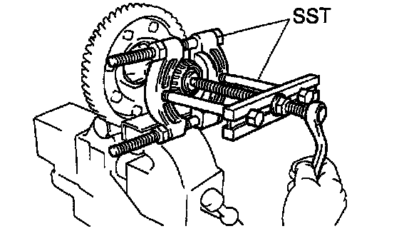
a. Using SST and a press, install a new side bearing to the transmission case side.
SST 09316-60011 (09316-00011), 09350-32014 (09351-32120)
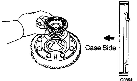
b. Install the vehicle speed sensor drive gear to the transaxle case side.

c. Using SST and a press, install a new side bearing to the transaxle case side.
SST 09316-60011 (09316-00011), 09350-32014 (09351-32120)
NOTICE: Install the black cage bearing on the vehicle speed sensor drive gear side.
4. ADJUST DIFFERENTIAL CASE SIDE BEARING PRELOAD
a. Install the differential to the transaxle case.
b. Install the transmission case.
c. Install and torque the case bolts.
Torque: 29 Nm (300 kgf-cm, 22 ft. lbs.)
d. Install the shim into the transmission case.
e. Install the bearing retainer without an O-ring.
f. Install and torque the 6 bolts.
Torque: 18 Nm (185 kgf-cm, 13 ft. lbs.)
g. Using SST and a torque wrench, measure the preload.
SST 09564-32011
Preload (at starting): 0.8 - 1.6 Nm (8 - 16 kgf-cm, 6.9 - 13.9 inch lbs.)
If the preload is not within the specification, remove the transmission case side bearing retainer. Select another shim.

HINT: The preload will change by approx. 0.3 - 0.4 Nm (3 - 4 kgf-cm, 2.6 - 3.5 inch lbs.) corresponding to each 0.05 mm (0.0019 inch) change in shim thickness.
h. Remove the 6 bolts.
i. Remove the bearing retainer and shim.
j. Remove the 17 bolts.
k. Remove the transmission case.
SHIFT LEVER AND CONTROL CABLE

Components