Timing Belt: Service and Repair


REMOVAL
1. DISCONNECT PS RESERVOIR AND REMOVE RESERVOIR BRACKET
2. DISCONNECT WIRE HARNESS BRACKET FOR
3. REMOVE GENERATOR
4. REMOVE GENERATOR BRACKET
5. w/ ABS: REMOVE NO. 3 ABS ACTUATOR BRACKET
6. REMOVE RH FRONT WHEEL
7. REMOVE RH ENGINE UNDER COVER
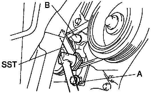
8. REMOVE PS PUMP DRIVE BELT
a. Loosen the bolt A.
b. Using SST and a deep socket wrench, loosen the bolt B.
SST SST 09249-63010
c. Remove the drive belt.
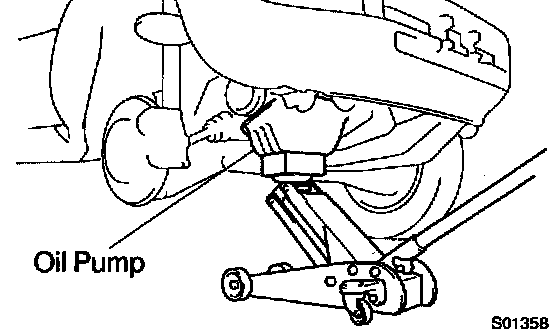
9. SLIGHTLY JACK UP ENGINE
Attach the jack to the oil pan, and raise the engine enough to remove the weight from the engine mounting on the right side.
10. REMOVE RH ENGINE MOUNTING INSULATOR
11. REMOVE SPARK PLUGS
12. REMOVE CRANKSHAFT PULLEY
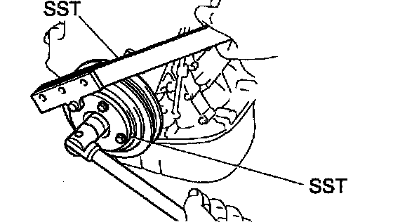
a. Using SST (and bolt), remove the pulley bolt.
SST 09213-54015 (91651-60855 for Type A), 09330-00021
Bolt: Part No. 91121-40665 for Type B
HINT:
- Either of 2 types of pulley may be used, each with its own bolt size, Type A and Type B.
- When using bolt Type B, a plate washer must be inserted between the bolt and SST.
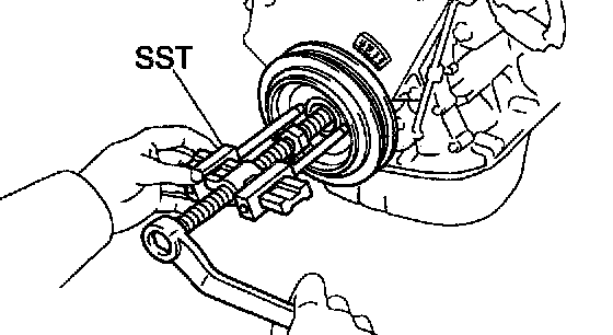
b. Using SST, remove the pulley.
SST 09950-50010 (09951-05010, 09952-05010, 09953-05010, 09953-05020, 09954-05020 for Type A, 09954-05010 for Type B)
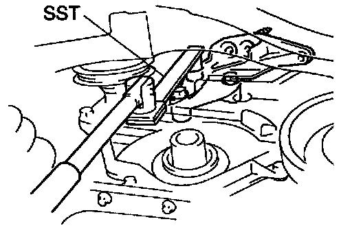
13. REMOVE RH ENGINE MOUNTING BRACKET
Using SST, remove the 3 bolts and mounting bracket.
SST 09249-63010
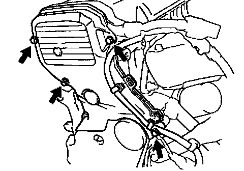
14. REMOVE NO. 2 TIMING BELT COVER
a. Disconnect the engine wire from the timing belt cover.
b. Remove the 4 bolts and timing belt cover.
15. TEMPORARILY INSTALL CRANKSHAFT PULLEY
a. Align the pulley set key with the key groove of the pulley, and slide on the pulley.
b. Temporarily install the pulley bolt.
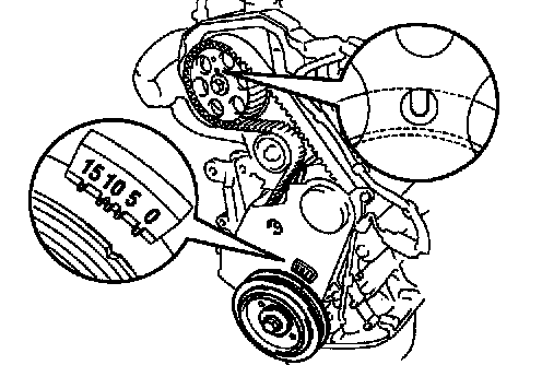
16. SET NO. 1 CYLINDER TO TDC/COMPRESSION
a. Turn the crankshaft pulley and align its groove with timing mark "0" of the No. 1 timing belt cover.
b. Check that the hole of the camshaft timing pulley is aligned with the timing mark of the bearing cap.
If not, turn the crankshaft 1 revolution (360°).
17. REMOVE TIMING BELT FROM CAMSHAFT TIMING PULLEY
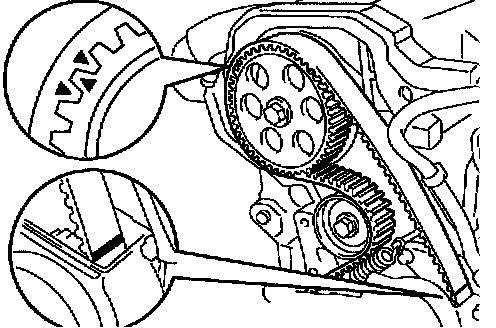
HINT: (When re-using timing belt): Place matchmarks on the timing belt and camshaft timing pulley, and place matchmark on timing belt to match the end of the No. 1 timing belt cover.
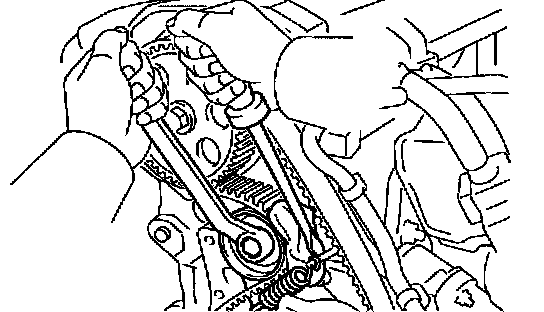
a. Loosen the mounting bolt of the No. 1 idler pulley and shift the pulley toward the left as far as it will go, and temporarily tighten it.
b. Remove the timing belt from the camshaft timing pulley.
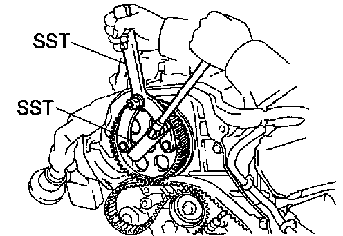
18. REMOVE CAMSHAFT TIMING PULLEY
Using SST, remove the pulley bolt and timing pulley.
SST 0924-63010, 09960-10010 (09962-10000, 09963-10000)
19. REMOVE CRANKSHAFT PULLEY
HINT: (When re-using timing belt): Remove the pulley without turning it.
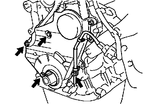
20. REMOVE NO. 1 TIMING BELT COVER
a. Disconnect the engine wire from the timing belt cover.
b. Remove the 4 bolts and timing belt cover.
21. REMOVE TIMING BELT GUIDE
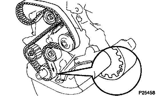
22. REMOVE TIMING BELT
HINT: (When re-using timing belt): Draw a direction arrow on the timing belt (in the direction of engine revolution), and place matchmarks on the timing belt and crankshaft timing pulley.
23. REMOVE NO. 1 IDLER PULLEY AND TENSION SPRING
24. REMOVE NO. 2 IDLER PULLEY
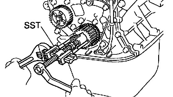
25. REMOVE CRANKSHAFT TIMING PULLEY
If the pulley cannot be removed by hand, use SST to remove the timing pulley.
SST 09950-50012 (09951-05010, 09952-5010, 09953-05010, 09953-05020, 09954-05010)
NOTICE: Do not scratch the angle sensor of the timing pulley.
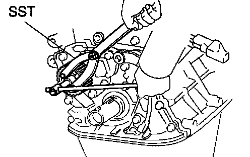
26. REMOVE OIL PUMP PULLEY
Using SST, remove the nut and pulley.
SST 09960-10010 (09962-01000, 09963-06000)
INSPECTION
1. INSPECT TIMING BELT

NOTICE:
- Do not bend, twist or turn the timing bell inside out.
- Do not allow the timing belt to come into contact with oil, water or steam.
- Do not utilize timing belt tension when installing or removing the mounting bolt of the camshaft timing pulley.
If there are any defects as shown in the illustration, check these points:
a. Premature parting
- Check for proper installation.
- Check the timing cover gasket for damage and proper installation.
b. If the belt teeth are cracked or damaged, check to see if either camshaft or water pump is locked.
c. If there is noticeable wear or cracks on the belt face, check to see if there are nicks on the side of the idler pulley lock.
d. If there is wear or damage on only one side of the belt, check the belt guide and the alignment of each pulley.
e. If there is noticeable wear on the belt teeth, check the timing cover for damage, correct gasket installation, and for foreign material on the pulley teeth.
If necessary, replace the timing belt.
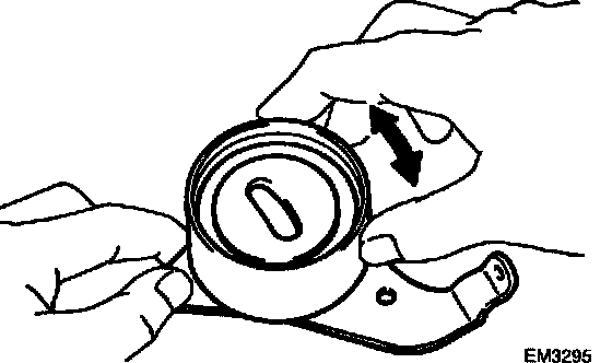
2. INSPECT IDLER PULLEYS
Check that the idler pulley turns smoothly.
If necessary, replace the idler pulley.
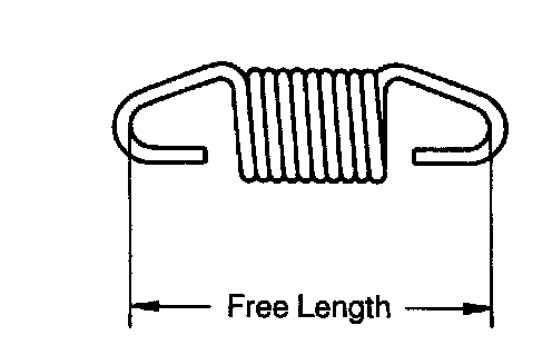
3. INSPECT TENSION SPRING
a. Measure the free length of tension spring.
Free length: 42.0 mm (1.653 inch)
If the free length is not as specified, replace the tension spring.
b. Measure the tension of the tension spring at the specified installed length.
Installed tension (at 50.5 mm (1.988 inch)): 31 - 38 Nm (3.15 - 3.85 kgf, 7.0 - 8.5 lbs.)
If the installed tension is not as specified, replace the tension spring.
INSTALLATION
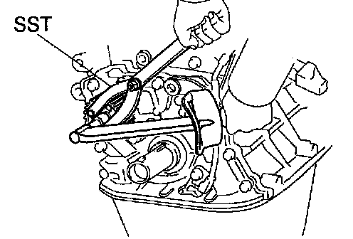
1. INSTALL OIL PUMP PULLEY
a. Align the cutouts of the pulley and shaft, and slide on the pulley.
b. Using SST, install the nut.
SST 09960-10010 (09962-01000, 09963-00600)
Torque: 24 Nm (245 kgf-cm, 18 ft. lbs.)
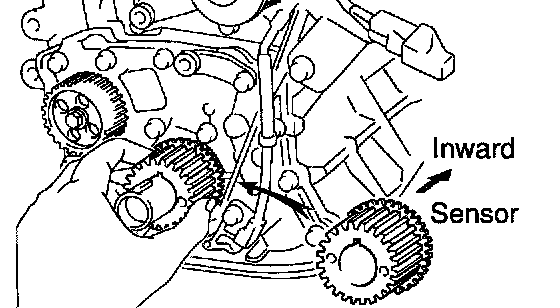
2. INSTALL CRANKSHAFT TIMING PULLEY
a. Align the timing pulley set key with the key groove of the pulley.
b. Install the timing pulley, facing the sensor side inward.
NOTICE: Do not scratch the sensor part of the crankshaft timing pulley.
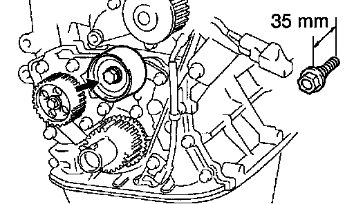
3. INSTALL NO. 2 IDLER PULLEY
a. Install the pulley with the bolt.
Torque: 42 Nm (425 kgf-cm, 31 ft. lbs.)
HINT: Use a bolt 35 mm (1.38 inch) in length.
b. Check that the idler pulley moves smoothly.
4. TEMPORARILY INSTALL NO. 1 IDLER PULLEY AND TENSION SPRING
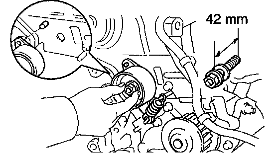
a. Align the bracket pin hole with the pivot pin.
b. Install the pulley with the bolt. Do not tighten the bolt yet.
HINT: Use a bolt 42 mm (1.65 inch) in length.
c. Install the tension spring.
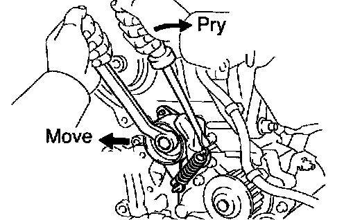
d. Pry the pulley toward the left as far as it will go and tighten the bolt.
e. Check that the idler pulley moves smoothly.
5. TEMPORARILY INSTALL TIMING BELT
NOTICE: The engine should be cold.

a. Using the crankshaft pulley bolt, turn the crankshaft and position the key groove of the crankshaft timing pulley upward.
b. Remove any oil or water on the crankshaft pulley, oil pump pulley, water pump pulley, No. 1 idler pulley and No. 2 idler pulley, and keep them clean.
c. Install the timing belt on the crankshaft timing pulley, oil pump pulley, No. 1 idler pulley, water pump pulley and No. 2 idler pulley.

HINT: (When re-using timing belt): Align the points marked during removal, and install the belt with the arrow pointing in the direction of engine revolution.
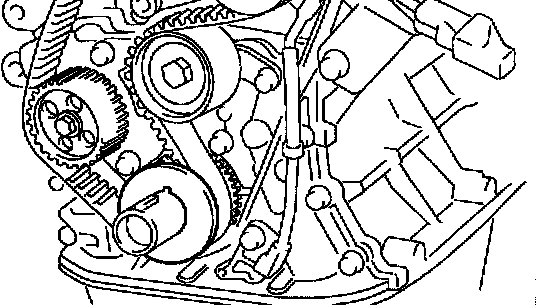
6. INSTALL TIMING BELT GUIDE
Install the guide, facing the cup side outward.
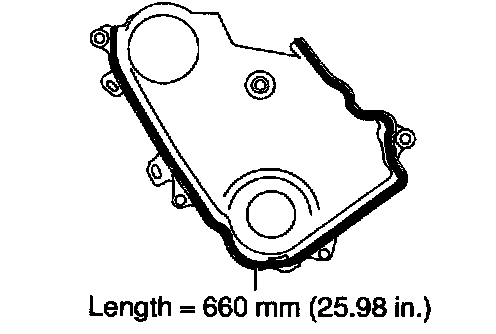
7. INSTALL NO. 1 TIMING BELT COVER
a. Check that the timing belt cover gaskets has no cracks or peeling, etc.
If the gasket has cracks or peeling, etc., replace it using these steps:
- Using a screwdriver and gasket scraper, remove all the old gasket material.
- Thoroughly clean all components to remove all the loose material.
- Remove the backing paper from a new gasket and install the gasket evenly to the part of the timing belt cover shaded black in the illustration.
- After installing the gasket, press down on it so that the adhesive firmly sticks to the timing belt cover.
b. Install the timing belt cover with the 5 bolts.
c. Install the engine wire to the timing belt cover.
8. TEMPORARILY INSTALL CRANKSHAFT PULLEY
a. Align the pulley set key with the key groove of the pulley, and slide on the pulley.
b. Temporarily install the pulley bolt.
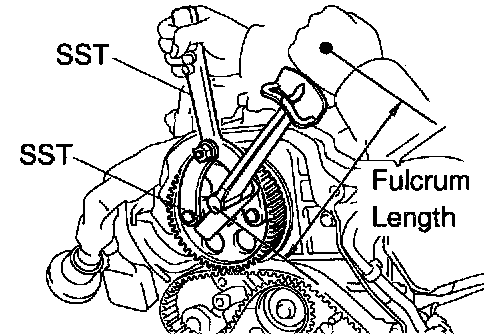
9. INSTALL CAMSHAFT TIMING PULLEY
a. Align the camshaft knock pin with the knock pin groove of the pulley, and slide on the timing pulley.
b. Using SST, install the bolt.
SST 09249-63010, 09960-10010 (09962-1000, 09963-01000)
Torque:
54 Nm (550 kgf-cm, 40 ft. lbs.)
37 Nm (380 kgf-cm, 27 ft. lbs.) for SST
HINT: Use a torque wrench with a fulcrum length of 340 cm (13.39 inch).
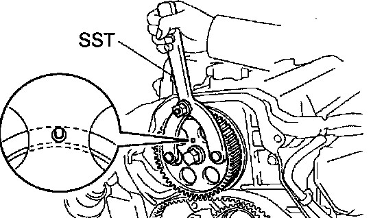
10. SET NO. 1 CYLINDER TO TDC/COMPRESSION
a. Turn the crankshaft pulley, and align its groove with timing mark "0" of the No. 1 timing belt cover.
b. Using SST, turn the camshaft, and align the hole of the camshaft timing pulley with the timing mark of the bearing cap.
SST 0996-10010 (09962-01000, 09963-01000)
11. INSTALL TIMING BELT

HINT: (When re-using timing belt): Check that the matchmark on the timing belt matches the end of the No. 1 timing belt cover.
If the matchmark does not align, align as follows:

- When matchmark is misaligned clockwise:
Align the matchmark by pulling the timing belt up on the water pump pulley side while turning the crankshaft pulley counterclockwise.

- When matchmark is misaligned clockwise: After aligning the matchmark, hold the timing belt, turn the crankshaft pulley clockwise, and align its groove with timing mark "0" of the No. 1 timing belt cover.

- When matchmark is misaligned counterclockwise: Align the matchmark by pulling the timing belt up on the No. 1 idler pulley side while turning the crankshaft pulley clockwise.

- When matchmark is misaligned counterclockwise: After aligning the matchmark, hold the timing belt, turn the crankshaft pulley counterclockwise, and align its groove with timing mark "0" of the No. 1 timing belt cover.
a. Remove any oil or water on the camshaft timing pulley, and keep it clean.

b. Align the matchmarks of the timing belt and camshaft timing pulley.
c. Install the timing belt, and check the tension between the crankshaft timing pulley and camshaft timing pulley.
12. CHECK VALVE TIMING
a. Loosen the No. 1 idler pulley bolt 1/2 turn.

b. Slowly turn the crankshaft pulley 2 revolutions from TDC to TDC.
NOTICE: Always turn the crankshaft clockwise.

c. Check that each pulley aligns with the timing marks as shown in the illustration. If the timing marks do not align, remove the timing belt and reinstall it.

d. Slowly turn the crankshaft pulley 1 and 7/8 revolutions, and align its groove with the mark at 45° BTDC (for No. 1 cylinder) of the No. 1 timing belt cover.
NOTICE: Always turn the crankshaft clockwise.
e. Torque the mounting bolt of the No. 1 idler pulley.
Torque: 42 Nm (425 kgf-cm, 31 ft. lbs.)
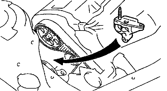
13. PLACE RH ENGINE MOUNTING BRACKET IN POSITION
HINT: Do not install the bolts.
14. INSTALL NO. 2 TIMING BELT COVER
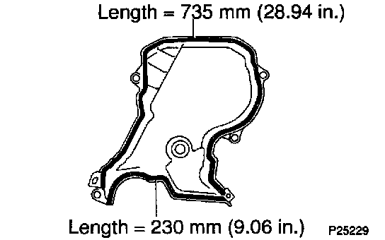
a. Check that the timing belt cover gaskets has no cracks or peeling, etc.
If the gasket has cracks or peeling, etc., replace it using these steps:
- Using a screwdriver and gasket scraper, remove all the old gasket material.
- Thoroughly clean all components to remove all the loose material.
- Remove the backing paper from a new gasket and install the gasket evenly to the part of the timing belt cover shaded black in the illustration.
- After installing the gasket, press down on it so that the adhesive firmly sticks to the timing belt cover.
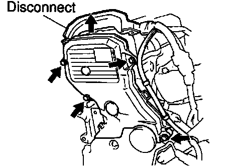
b. Disconnect the engine wire protector between the cylinder head cover and No. 3 timing belt cover.
c. Install the No. 2 timing belt cover with the 4 bolts.
d. Install the engine wire to the No. 2 timing belt cover.
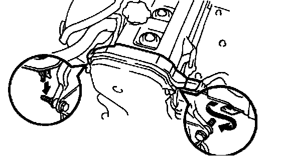
e. Install the engine wire protector to the 2 mounting bolts of the No. 2 timing belt cover in the sequence shown.
15. REMOVE CRANKSHAFT PULLEY
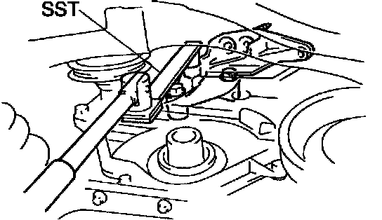
16. INSTALL RH ENGINE MOUNTING BRACKET
Using SST, install the mounting bracket with 3 bolts.
SST 09249-63010
Torque:
52 Nm (530 kgf-cm, 38 ft. lbs.)
35 Nm (360 kgf-cm, 26 ft. lbs.) for SST
HINT: Use a torque wrench with a fulcrum length of 340 mm (13.39 inch)
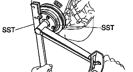
17. INSTALL CRANKSHAFT PULLEY
a. Align the pulley set key with the key groove of the pulley, and slide on the pulley.
b. Using SST (and bolt), install the pulley bolt.
SST 09213-54015 (91651-60855 for Type A), 09330-00021
Bolt: Part No. 91121-40665 for Type B
Torque: 108 Nm (1,100 kgf-cm, 80 ft. lbs.)
18. INSTALL SPARK PLUGS
19. INSTALL RH ENGINE MOUNTING INSULATOR
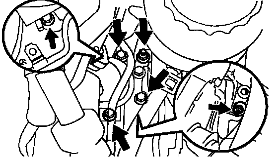
a. Attach the mounting insulator to the body and mounting bracket with the 4 bolts and 2 nuts.
b. Tighten the 3 bolts holding the mounting insulator to the body.
Torque: 52 Nm (530 kgf-cm, 38 ft. lbs.)
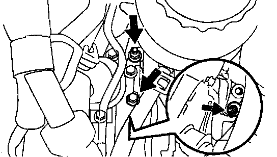
c. Tighten the 2 nuts and bolt holding the mounting insulator to the mounting bracket.
Torque:
Bolt 37 Nm (380 kgf-cm, 27 ft. lbs.)
Nut 52 Nm (530 kgf-cm, 38 ft. lbs.)
20. INSTALL AND ADJUST PS PUMP DRIVE BELT
21. INSTALL RH ENGINE UNDER COVER
22. INSTALL RH FRONT WHEEL
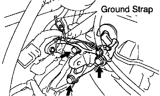
23. w/ ABS: INSTALL NO. 3 ABS ACTUATOR BRACKET
24. INSTALL GENERATOR BRACKET
a. Install the bracket with the 3 bolts.
Torque: 42 Nm (425 kgf-cm, 31 ft. lbs.)
b. Connect the ground strap connector.
25. INSTALL GENERATOR
26. INSTALL WIRE HARNESS BRACKET FOR DLC1
27. INSTALL PS RESERVOIR BRACKET AND RESERVOIR