Differential Assembly
DIFFERENTIAL ASSEMBLYCOMPONENTS
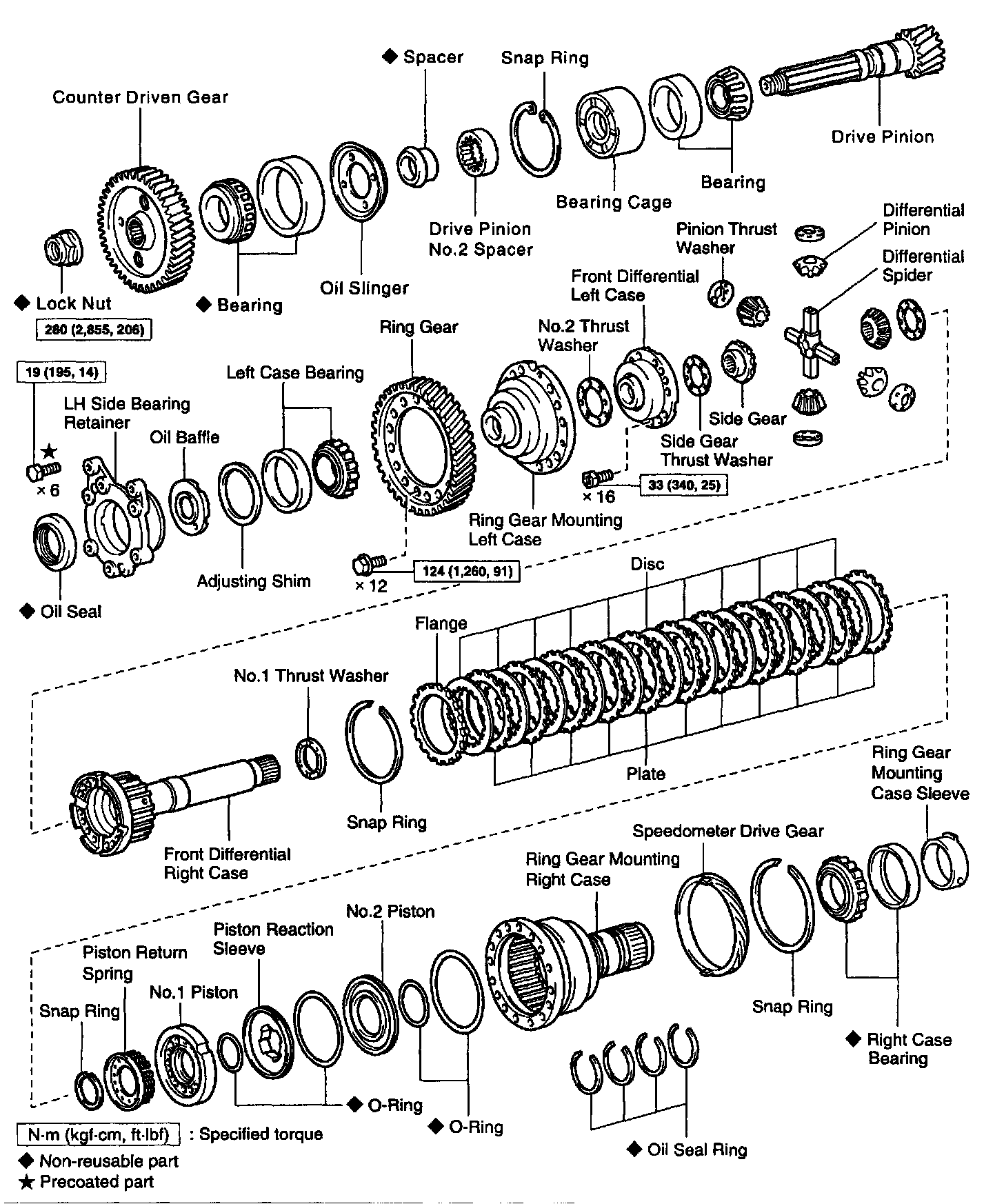
DIFFERENTIAL DISASSEMBLY
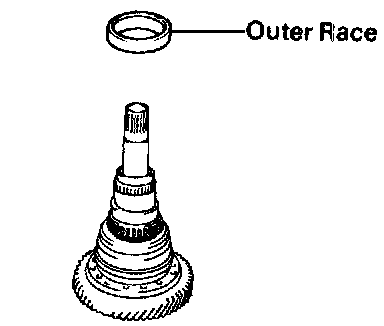
1. REMOVE RIGHT SIDE BEARING OUTER RACE
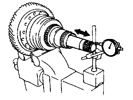
2. CHECK DIFFERENTIAL END PLAY
Using a dial indicator, measure the differential end play.
End play: 0.18 - 0.82 mm (0.0071 - 0.0323 inch)
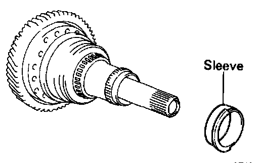
3. REMOVE RING GEAR MOUNTING CASE SLEEVE
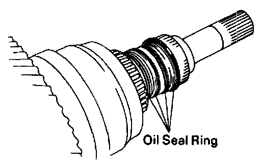
4. REMOVE OIL SEAL RINGS
Remove the 4 oil seal rings from the ring gear mounting right case.
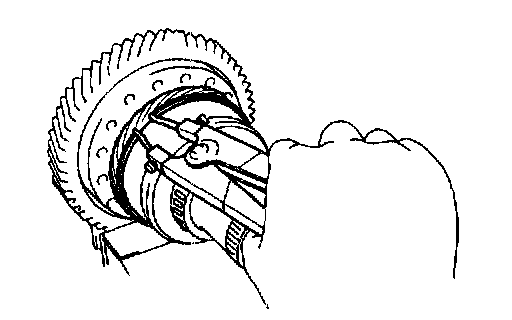
5. REMOVE SPEEDOMETER DRIVE GEAR
Using a snap ring expander, remove the snap ring and the speedometer drive gear.
6. REMOVE RING GEAR MOUNTING LEFT CASE
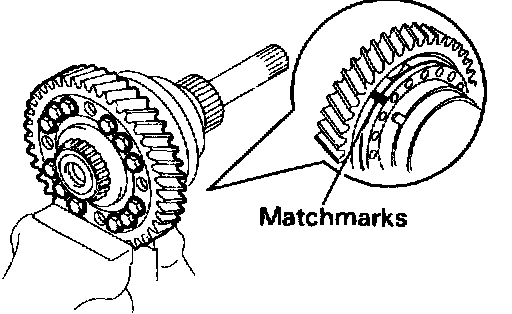
a. Place matchmarks on the ring gear mounting left case and right case.
b. Remove the 12 bolts and left case.
7. REMOVE RING GEAR
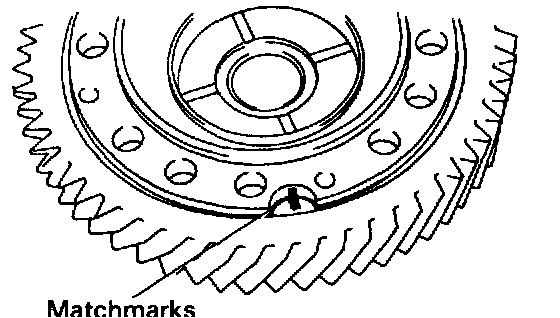
a. Place matchmarks on the ring gear and left case.
b. Place the left case on SST.
SST 09350-32014 (09351-32090)
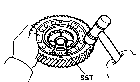
c. Using a plastic hammer, remove the ring gear from the left case.
8. REMOVE FRONT DIFFERENTIAL CASE
a. Remove the No.2 thrust washer.
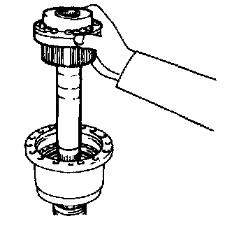
b. Remove the front differential case from the ring gear mounting right case.
9. REMOVE FRONT DIFFERENTIAL LEFT CASE
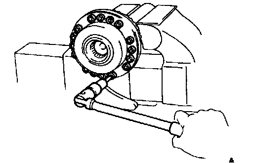
a. Using a torx wrench, remove the 16 screws from the left case.
(Torx socket wrench T40 09042-00020)
b. Separate the left case and right case.
NOTICE: Do not scratch the contact surface of the needle bearing.
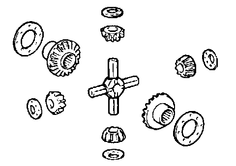
10. REMOVE DIFFERENTIAL PINIONS AND SIDE
GEARS
Remove the following parts:
- 4 pinion washers
- 4 differential pinions
- Differential spider
- 2 side thrust washers
- 2 differential side gears
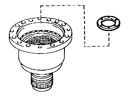
11. REMOVE NO.1 THRUST WASHER
12. CHECK OPERATION OF CLUTCH PISTONS
a. Plug one hole of the right case with your hand.
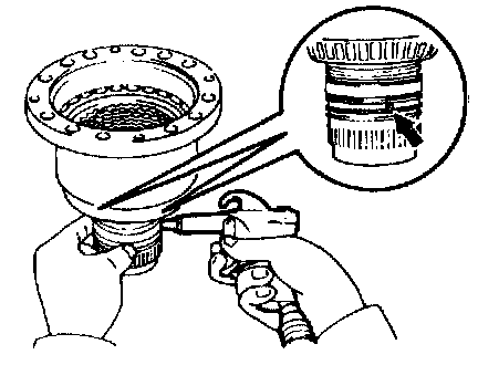
b. Blow compressed air into the other hole and confirm that the pistons move.
13. REMOVE HYDRAULIC MULTIPLATE CLUTCH DISCS AND PLATES
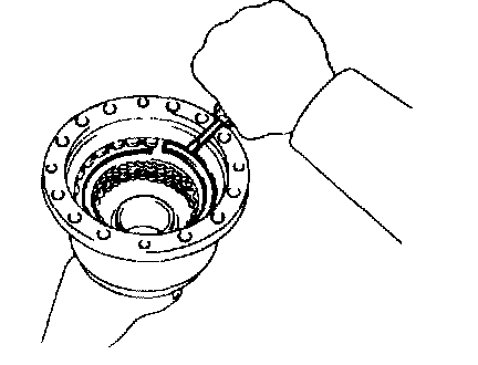
a. Using a screwdriver, remove the snap ring.
b. Remove the flange, 11 discs and plates.
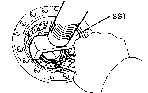
c. Place SST, and compress the return spring.
SST 09350-32014 (09351-32070)
d. Using a snap ring expander, remove the snap ring.
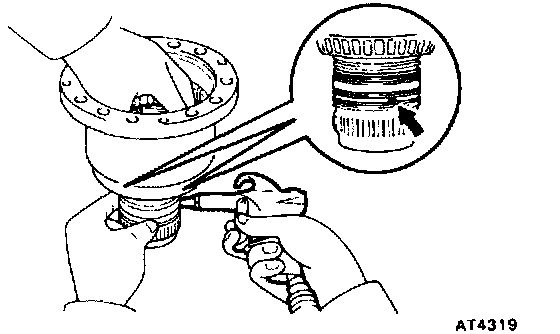
e. Blow compressed air to the right case hole to remove the No.1 piston.
f. Remove the O-ring from the No.1 piston.
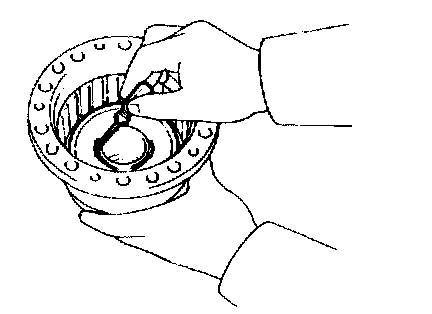
g. Using a small screwdriver, remove the reaction sleeve and No.2 piston.
h. Remove the 3 O-rings from the reaction sleeve and No.2 piston.
RING GEAR MOUNTING CASE BEARINGS REPLACEMENT
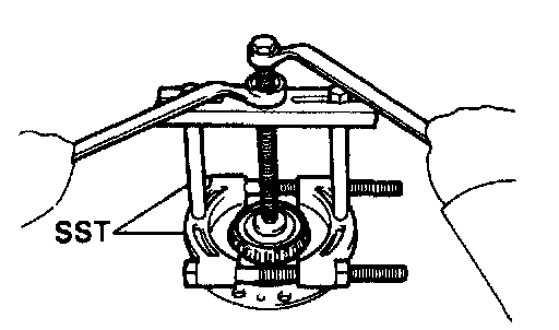
1. REMOVE RING GEAR MOUNTING LEFT CASE BEARING
Using SST, remove the bearing.
SST 09950-00020, 09950-00030
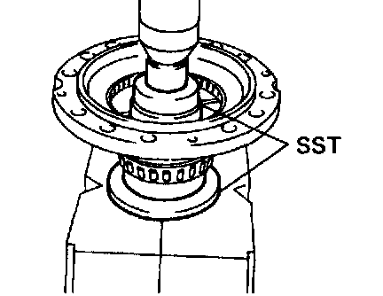
2. INSTALL RING GEAR MOUNTING LEFT CASE BEARING
Using SST and a press, press in the bearing.
SST 09316-20011, 09350-32014 (09351-32090)
3. REMOVE RING GEAR MOUNTING RIGHT CASE BEARING
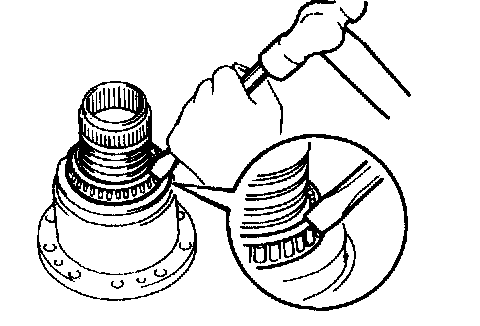
a. Using a chisel and hammer, cut out the bearing cage.
NOTICE: Do not damage the right case.
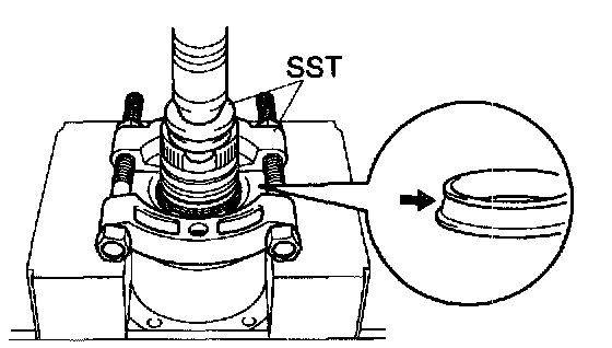
b. Using SST and a press, press out the bearing inner race.
SST 09350-32014 (09351-32090), 09950-00020
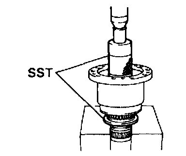
4. INSTALL RING GEAR MOUNTING RIGHT CASE BEARING
Using SST and a press, press in the new bearing.
SST 09316-60011 (09316-00011), 09502-12010
5. REMOVE RING GEAR MOUNTING LEFT CASE BEARING OUTER RACE FROM LH BEARING RETAINER
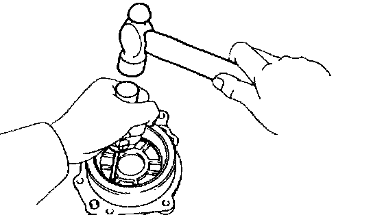
a. Using a screwdriver and hammer, remove the oil seal.
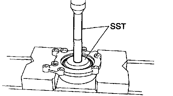
b. Using SST and a press, press out the oil baffle, outer race and adjusting shim from LH bearing retainer.
SST 09950-60020 (09951-00780), 09950-70010 (09951-07150)
6. INSTALL OIL BAFFLE, ADJUSTING SHIM AND BEARING OUTER RACE TO LH BEARING RETAINER
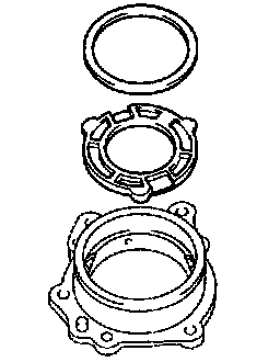
a. Place the oil baffle and adjusting shim into the LH bearing retainer.
HINT: Use either the shim which was removed a shim of 2.40 mm (0.0945 inch) thickness.
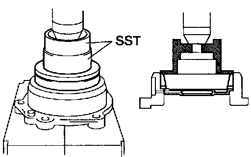
b. Using SST and a press, press the outer race into the LH retainer.
SST 09316-20011, 09350-32014 (09351-32150)
HINT: Install the oil seal after adjusting the differential side bearing preload.
HYDRAULIC MULTIPLATE CLUTCH INSPECTION
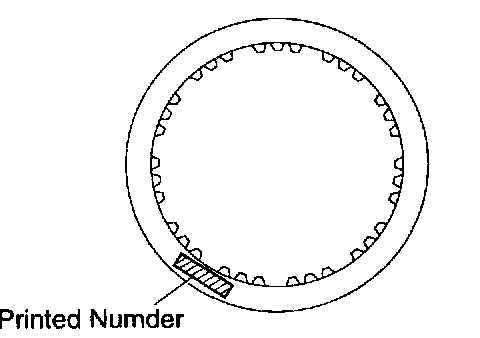
INSPECT DISCS, PLATES AND FLANGE
Check if the sliding surfaces of disc, plates and flange are worn or burnt If necessary, replace them.
HINT: If the lining of the disc is peeling off or discolored, or even if a part of the printed number is defaced, replace all discs.
DIFFERENTIAL ASSEMBLY
1. INSTALL PISTONS AND SLEEVE
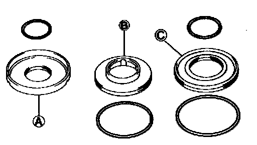
a. Coat new 4 O-rings with ATF.
b. Install the 4 O-rings to the reaction sleeve and pistons.
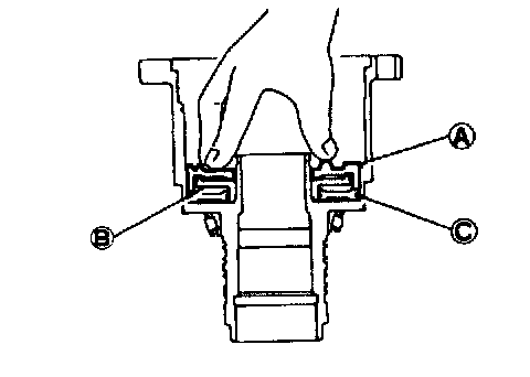
c. Install the No.1 (A) No.2 (B) pistons and reaction sleeve (C) to the ring gear mounting right case.
2. INSTALL PISTON RETURN SPRING
a. Place the spring on the piston.
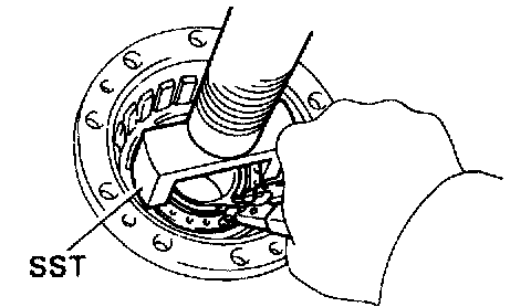
b. Place SST on the spring retainer, and compress the spring with a press.
SST 09350-32014 (09351-32070)
c. Using snap ring expander, install the snap ring.
3. INSTALL PLATES, DISCS AND FLANGE
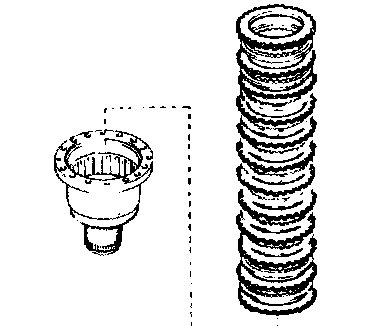
a. Install the plates and discs.
Install in order: P = Plate D = Disc
P-D-P-D-P-D-P-D-P-D-P-D-P-D-P-D-P-D-P-D-P-D
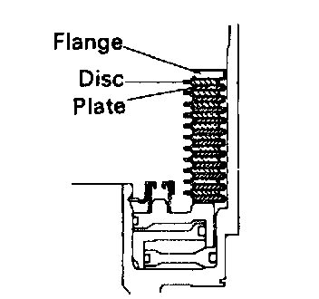
b. Install the flange with the flat end facing downward.
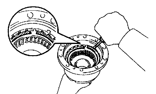
c. Using a screwdriver, install the snap ring.
4. CHECK OPERATION OF CLUTCH PISTONS
a. Plug one hole with your hand.
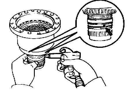
b. Blow compressed air into the other hole and make sure that the pistons move.
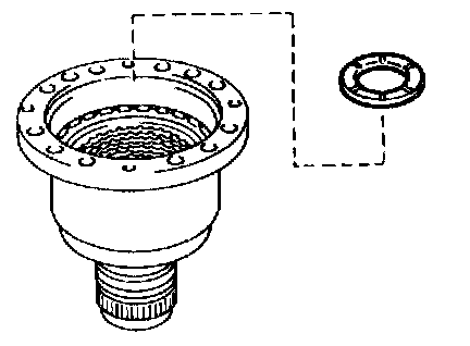
5. INSTALL NO.1 THRUST WASHER
6. CHECK AND ADJUST FRONT DIFFERENTIAL SIDE GEAR BACKLASH
Front Differential Left Case
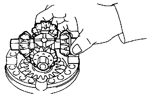
a. Install the following parts:
- Side gear thrust washer
- Side gear
- 4 differential pinion gears
- 4 pinion gear thrust washers
- Differential spider
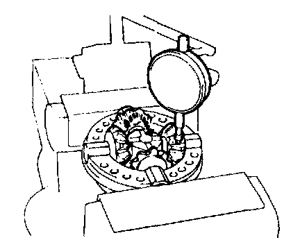
b. Using a dial indicator, measure the backlash of one pinion gear while holding the side gear toward the case.
Backlash: 0.05 - 0.20 mm (0.0020 - 0.0079 inch)
If not within specification, select the side gear thrust washer.
NOTICE: Do not tighten the vise too tight.
c. Remove the 4 pinion gears, thrust washers and spider.
Front Differential Right Case
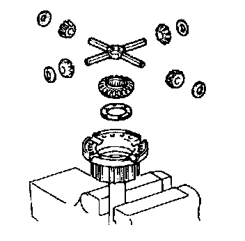
a. Install the following parts:
- Side gear thrust washer
- Side gear
- 4 differential pinion gears
- 4 pinion gear thrust washers
- Differential spider
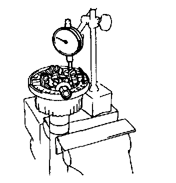
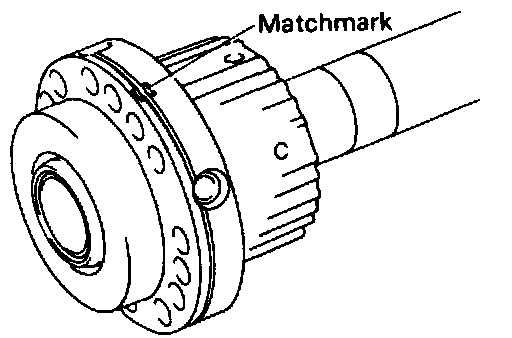
b. Using a dial indicator, measure the backlash of one pinion gear while holding the side gear toward the case.
Backlash: 0.05 - 0.20 mm (0.0020 - 0.0079 inch)
Referring to the table, select the side gear thrust washer which will ensure that the backlash is within specification. Try to select a washer of the same size.
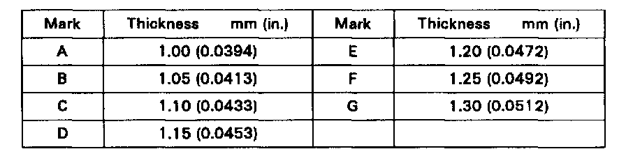
Thrust washer thickness
7. INSTALL FRONT DIFFERENTIAL LEFT CASE
a. Align the matchmarks on the left case and right case, install the left case to the right case.
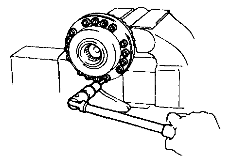
b. Using a torx wrench, torque the 16 torx screws. (Torx socket wrench T40 09042 - 00020)
Torque: 33 Nm (340 kgf-cm, 25 ft. lbs.)
NOTICE: Do not scratch the contact surface of the needle bearing.
8. INSTALL FRONT DIFFERENTIAL CASE
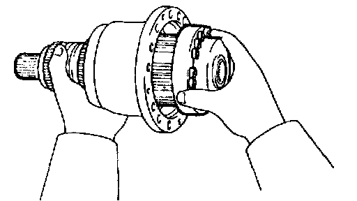
a. Install the front differential case to the ring gear mounting right case.
HINT: Align the flukes of the discs in the hydraulic multiplate clutch.
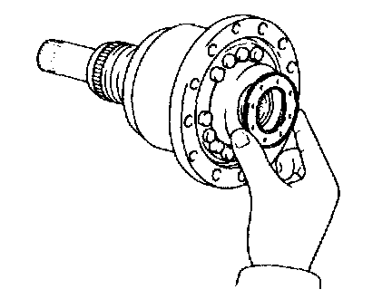
b. Install the No.2 thrust washer.
9. INSTALL RING GEAR
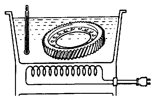
a. Clean the contact surface of the ring gear mounting left case.
b. Heat the ring gear to about 100°C (212°F) in an oil bath.
NOTICE: Do not heat the ring gear above 110°C (230°F).
c. Carefully remove the ring gear from the oil bath.
d. Clean the contact surface of the ring gear with cleaning solvent.
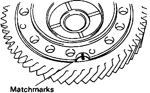
e. Quickly install the ring gear on the ring gear mounting left case.
HINT: Align the matchmarks on the ring gear mounting left case and the ring gear.
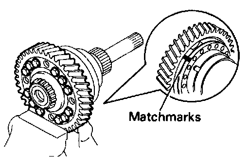
f. Align the matchmarks on the ring gear mounting left case and contact the right case, install the left case on the right case
g. Torque the 12 set bolts uniformly a little at a time.
Torque: 124 Nm (1,260 kgf-cm, 91 ft. lbs.)
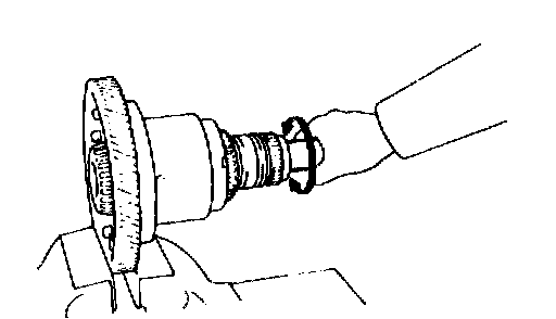
10. CHECK OPERATION OF FRONT DIFFERENTIAL
Check that the front differential turn smoothly.
11. INSTALL SPEEDOMETER DRIVE GEAR
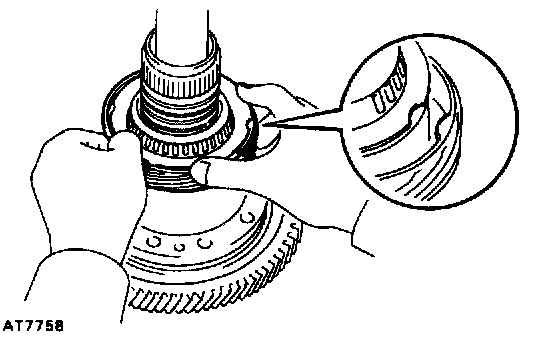
a. Place the speedometer drive gear on the ring gear mounting case.
b. Install the snap ring.
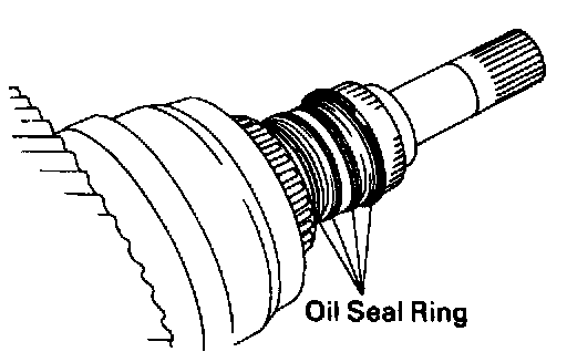
12. INSTALL OIL SEAL RINGS
Install the 4 oil seal rings to the ring gear mounting right case.
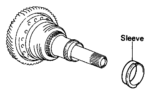
13. INSTALL RING GEAR MOUNTING CASE SLEEVE
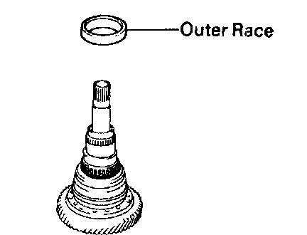
14. INSTALL RIGHT SIDE BEARING OUTER RACE