Knock Sensor: Description and Operation
P0325 - Knock Sensor 1 Circuit Malfunction (Bank 1)CIRCUIT DESCRIPTION
DTC Detection Condition:

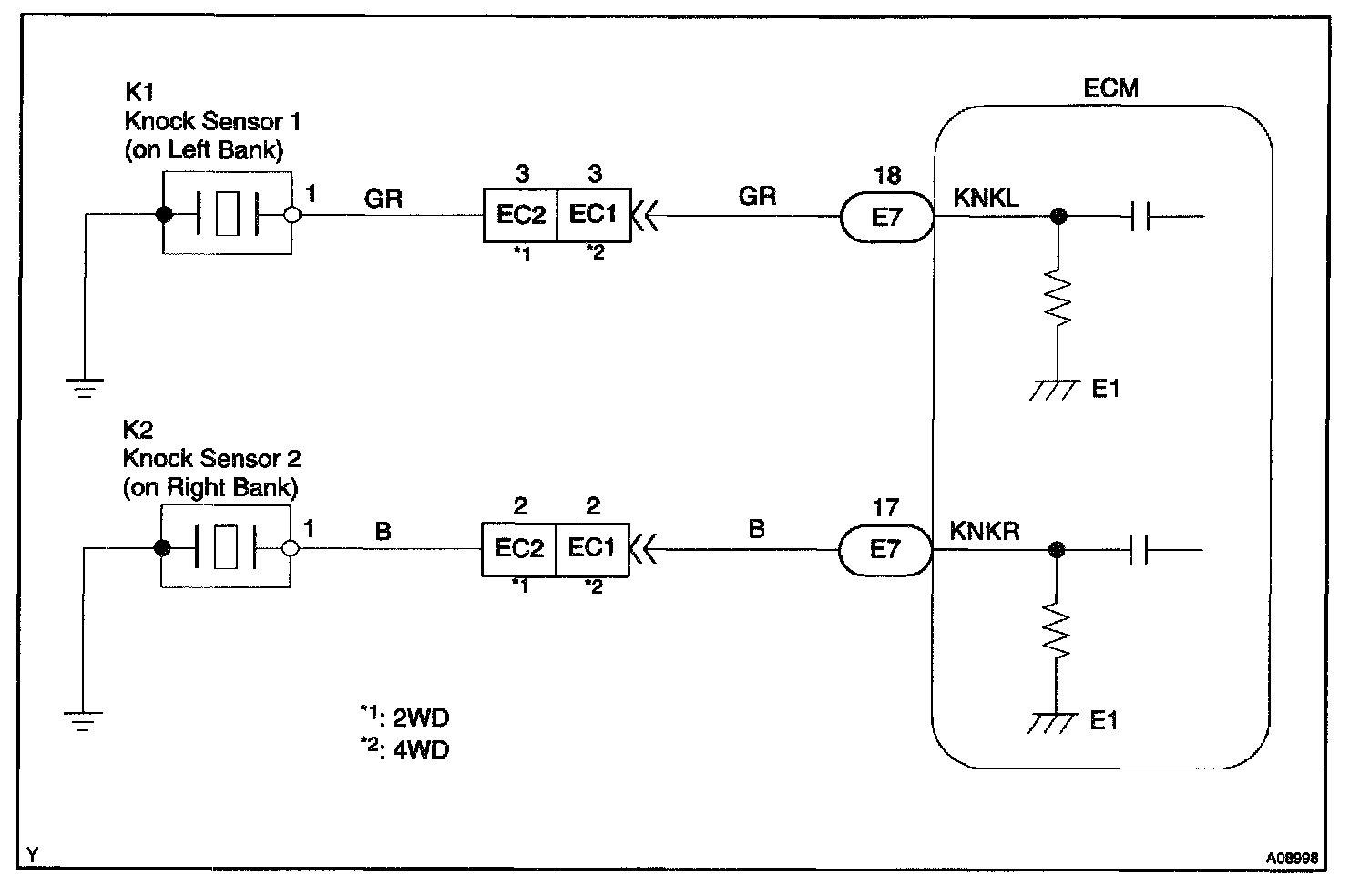
One of the knock sensors is fitted to the right bank and another to the left bank of the cylinder block to detect the engine knocking. This sensor contains a piezoelectric element which generates voltage when it becomes deformed. This occurs when the cylinder block vibrates due to knocking. If the engine knocking occurs, ignition timing is retarded to suppress it.
Wiring Diagram:
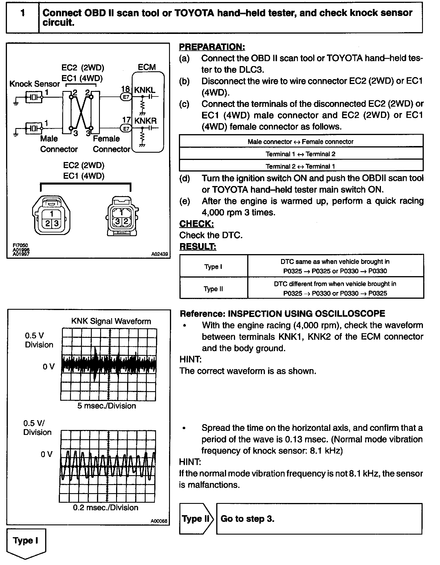
Step 1:
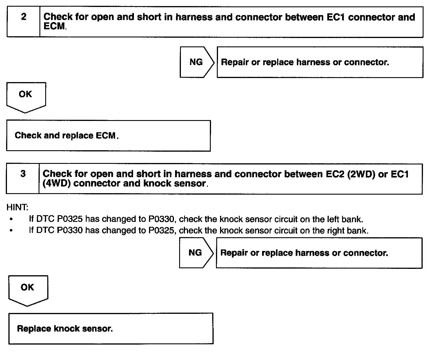
Steps 2 - 3:
INSPECTION PROCEDURE
HINT:
- DTC P0325 is for the left bank knock sensor circuit.
- DTC P0330 is for the right bank knock sensor circuit.
- Read freeze frame data using TOYOTA hand-held tester or OBD II scan tool, as freeze frame data records the engine conditions when a malfunction is detected. When troubleshooting it is useful for determining whether the vehicle was running or stopped, the engine was warmed up or not, the air-fuel ratio was lean or rich, etc. at the time of the malfunction.