Component Inspection
INSPECTION1. INTAKE AIR FLOW METER SUB-ASSY

a. Output voltage inspection.
1. Apply battery voltage across terminals 1 (+B) and 2 (E2G).
2. Using a voltmeter, connect the positive (+) tester probe to terminal VG, and negative (-) tester probe to terminal E2G.
3. Blow air into the MAF meter, and check that the voltage fluctuates.
b. Resistance inspection.
1. Using an ohmmeter, measure the resistance between terminals 4 (THA) and 5 (E2).
Resistance:
-20°C (-4°F) 13.6 - 18.4 kOhms
20°C (68°F) 2.21 - 2.69 kOhms
60°C (140°F) 0.493 - 0.667 kOhms
2. ACCELERATOR PEDAL ASSY
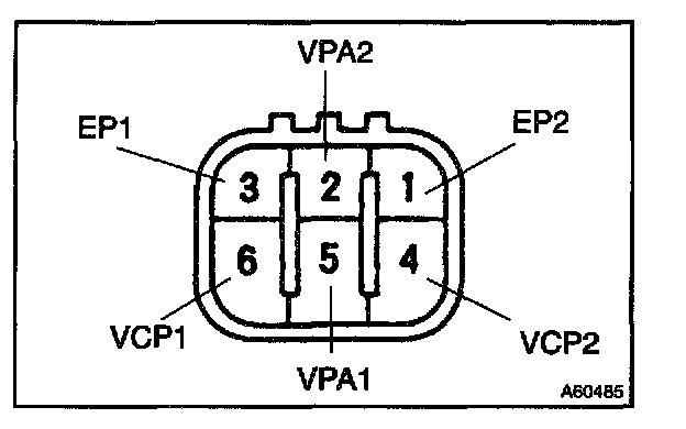
a. Resistance inspection
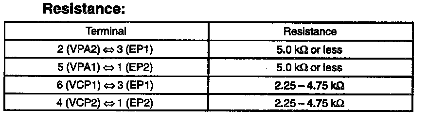
1. Using an ohmmeter, measure the resistance between terminals.
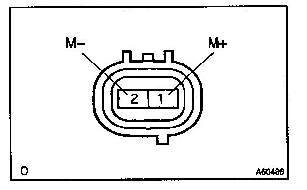
3. THROTTLE BODY ASSY
a. Resistance inspection
1. Using an ohmmeter, measure the resistance between terminals.
Resistance: 0.3 - 100 ohms at 20°C (68°F)

4. E.F.I. THROTTLE POSITION SENSOR
a. Resistance inspection.
1. Using an ohmmeter, measure the resistance between terminals 1 (VC) and 4 (E2).
Resistance: 1.2 - 3.2 kOhms

5. E.F.I. ENGINE COOLANT TEMPERATURE SENSOR
a. Resistance inspection.
1. Using an ohmmeter, measure the resistance between each terminal.
Resistance:
Approx. 20°C (68°F) 2.32- 2.59 kOhms
Approx. 80°C (176°F) 0.310 - 0.326 kOhms
NOTE: In case of checking the water temperature sensor in the water, be careful not to allow water to go into the terminals, and after checking, wipe out the sensor.

6. KNOCK CONTROL SENSOR
a. Continuity inspection.
1. Using an ohmmeter, check that no continuity exists between the terminal and body.

7. E.F.I. CIRCUIT OPENING RELAY ASSY
E.F.I ECU RELAY
AIR FUEL RATIO SENSOR HEATER RELAY
a. Continuity inspection.
1. Using an ohmmeter, check that continuity exists between each terminal.
Specified condition:
Between terminal 1 and 2 Continuity
Between terminal 3 and 5 No continuity
2. Using an ohmmeter, check that continuity exists between terminals 3 and 5 when the battery voltage is applied across terminals 1 and 2.