Heater Core Case: Service and Repair
AIR CONDITIONING RADIATOR ASSYOVERHAUL
1. DISCHARGE REFRIGERANT FROM REFRIGERATION SYSTEM
SST 07110-58060 (07117-58080, 07117-58090, 07117-78050, 07117-88060, 07117-88070, 07117-88080)
2. DISCONNECT COOLER REFRIGERANT SUCTION PIPE C
a. Install SST on piping clamp.
HINT: Make sure the direction of the piping clamp claw and SST by seeing the illustration shown on the caution label.
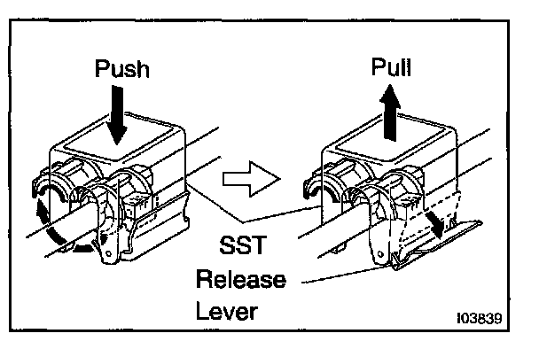
b. Push down SST and release the clamp lock.
NOTE: Be careful not to deform the tube when pushing SST.
c. Pull SST slightly and push the release lever, and then remove the piping clamp with SST.
SST 09870-00015
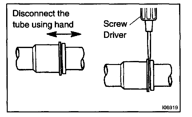
d. Disconnect the air conditioning tube assy.
NOTE:
- Do not use tools like screwdriver to remove the tube.
- Cap the open fittings immediately to keep moisture or dirt out of the system.
3. DISCONNECT COOLER REFRIGERANT LIQUID PIPE C
HINT: Disconnection of the cooler refrigerant liquid pipe C is same the cooler refrigerant suction pipe C.
SST 09870-00025
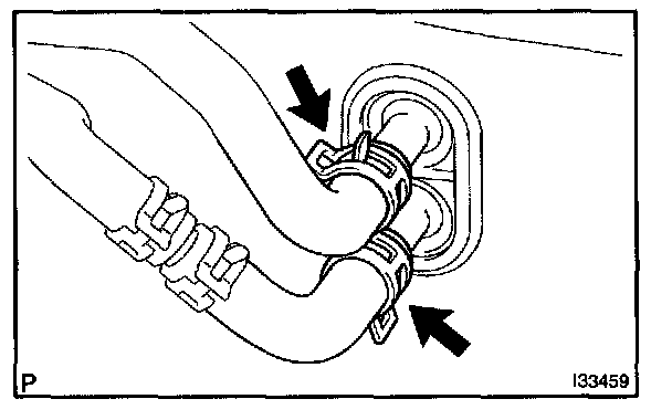
4. DISCONNECT HEATER WATER OUTLET HOSE A(FROM HEATER UNIT)
a. Using pliers, grip the claws of clip and slide the clip and disconnect the heater water outlet hose A (from heater unit).
5. DISCONNECT HEATER WATER INLET HOSE A
HINT: Disconnection of the heater water inlet hose A is same as the heater outlet hose A (from heater unit).
6. REMOVE INSTRUMENT PANEL SAFETY PAD SUB-ASSY
HINT: Refer to the instructions for removal of the instrument panel safety pad sub-assy.
7. REMOVE AIRCONDITIONER AMPLIFIER ASSY
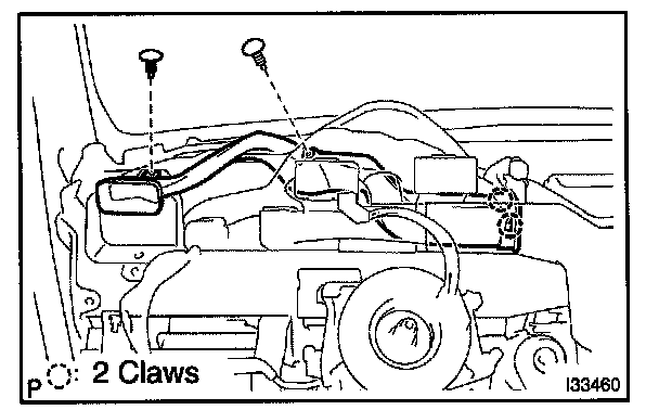
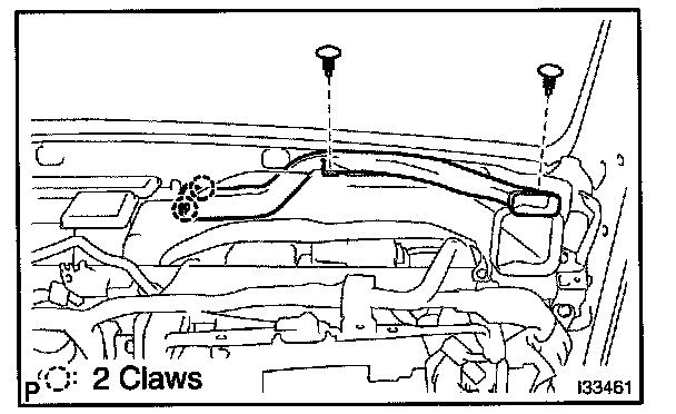
8. REMOVE SIDE DEFROSTER NOZZLE DUCT NO.1
a. Remove the 2 clips.
b. Release the 2 claw fittings and remove the side defroster nozzle duct No.1.
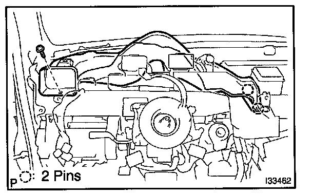
9. REMOVE SIDE DEFROSTER NOZZLE DUCT NO.2
a. Remove the 2 clips.
b. Release the 2 claw fittings and remove the side defroster nozzle duct No.2.
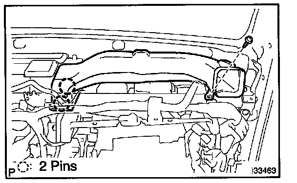
10. REMOVE HEATER TO REGISTER DUCT NO.1
a. Remove the screw.
b. Release the 2 pin fittings and remove the heater to register duct No.1.
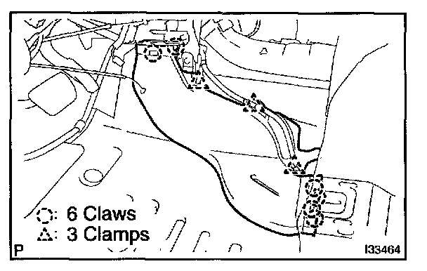
11. REMOVE HEATER TO REGISTER DUCT NO.3
a. Remove the screw.
b. Release the 2 pin fittings and remove the heater to register duct No.3.
12. REMOVE AIR DUCT REAR NO.1
a. Release the 6 claw fittings and 3 clamps and remove the air duct rear No.1.
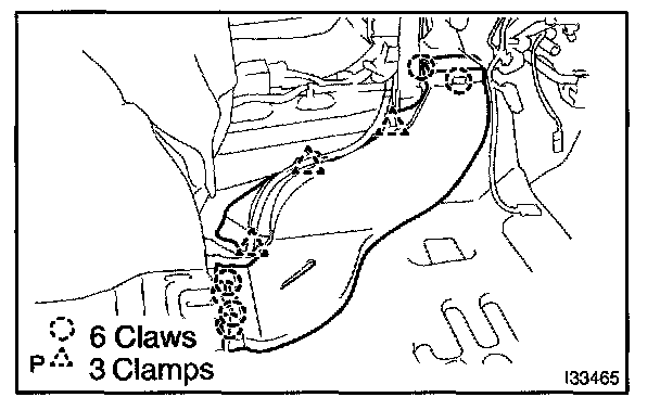
13. REMOVE AIR DUCT REAR NO.2
a. Release the 6 claw fittings and 3 clamps and remove the air duct rear No.2.
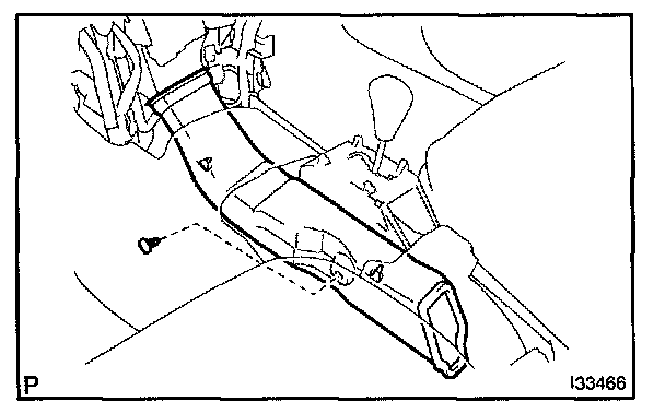
14. DISCONNECT CONSOLE BOX DUCT NO.1
a. Remove the clip and disconnect the console box duct No.1.
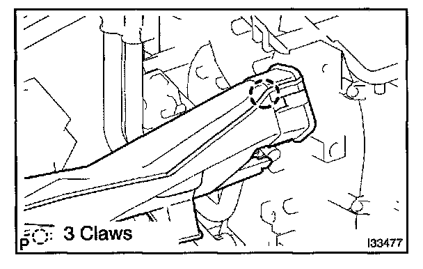
15. REMOVE AIR DUCT NO.1
a. Release the 3 claw fittings and remove the air duct No.1.
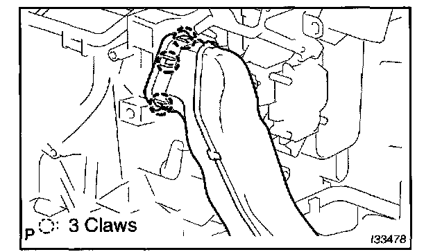
16. REMOVE AIR DUCT NO.2
a. Release the 3 claw fittings and remove the air duct No.2.
17. REMOVE INSTRUMENT PANEL BRACE MOUNTING BRACKET NO.1
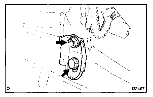
a. Remove the bolt, nut and instrument panel brace mounting bracket No.1.
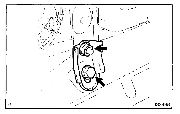
b. Remove the bolt, nut and instrument panel brace mounting bracket No.1.
18. DISCONNECT STEERING COLUMN ASSY
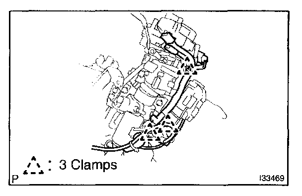
a. Release the 3 clamps and disconnect the connector.
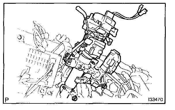
b. Remove the 4 nuts and disconnect the steering column assy.
19. REMOVE INSTRUMENT PANEL REINFORCEMENT
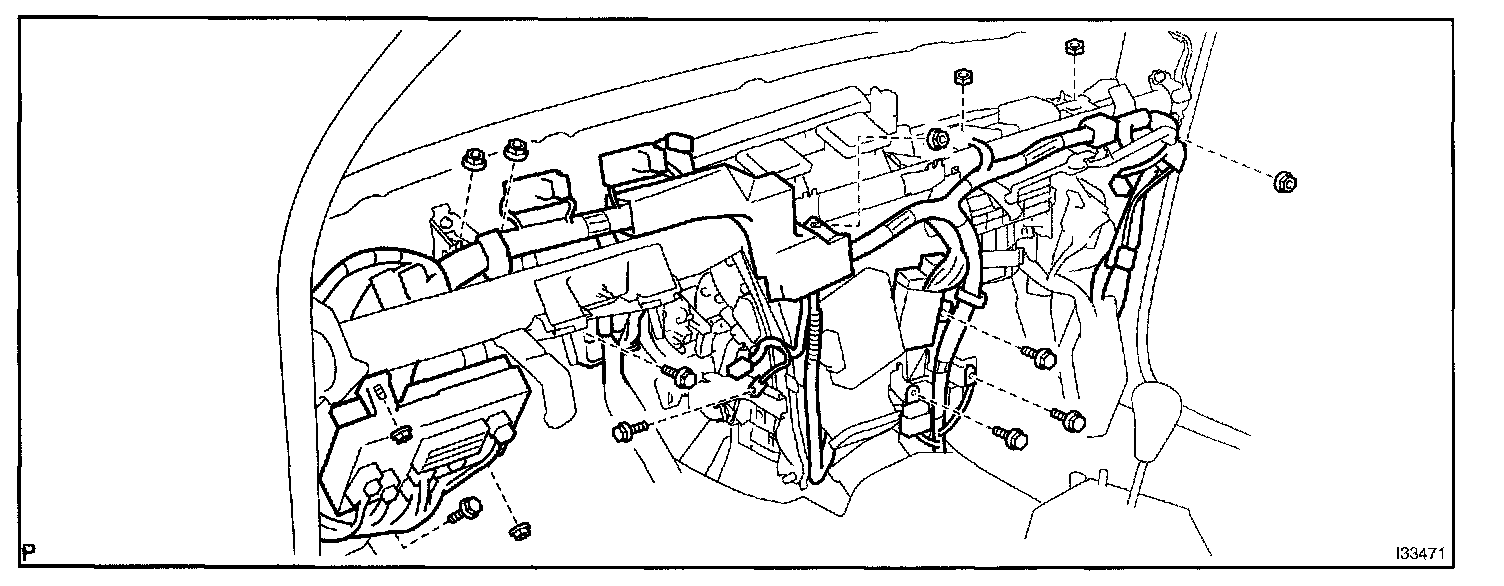
a. Remove the 6 bolts and 8 nuts.
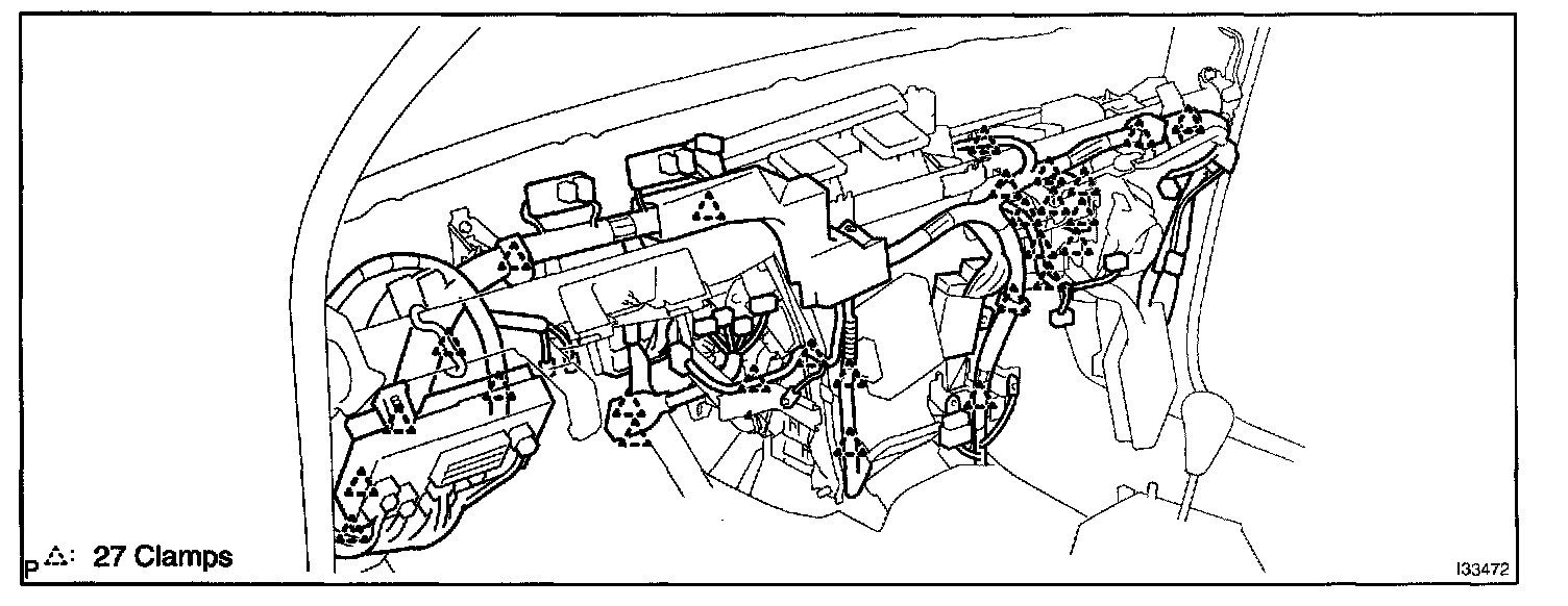
b. Release the 27 clamps.
c. Disconnect the connectors.
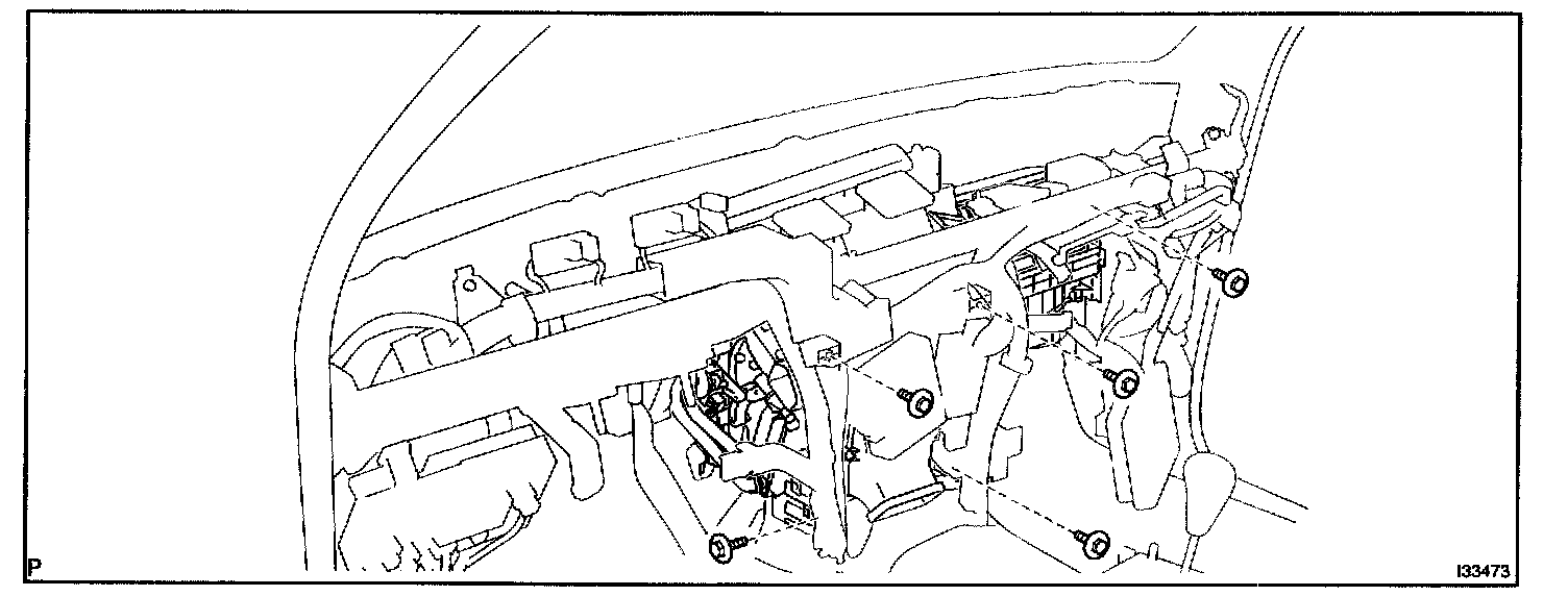
d. Remove the 5 bolts.
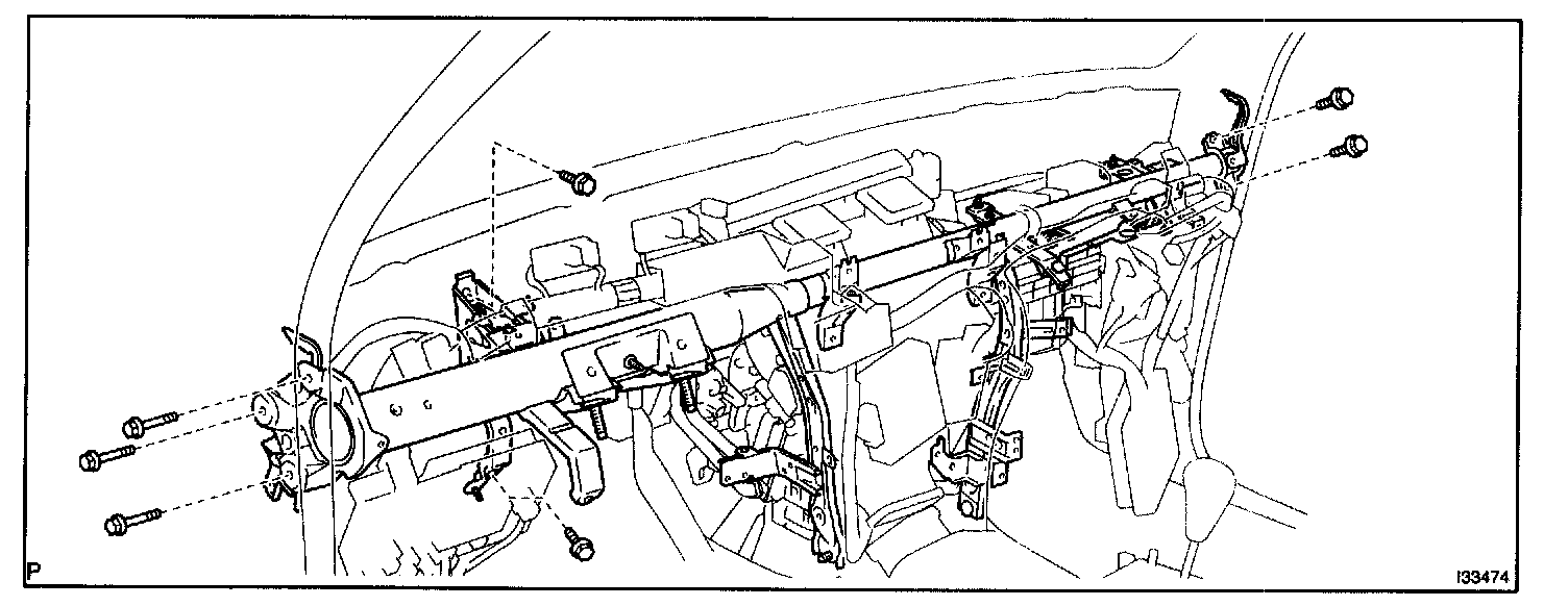
e. Remove the 7 bolts and instrument panel reinforcement
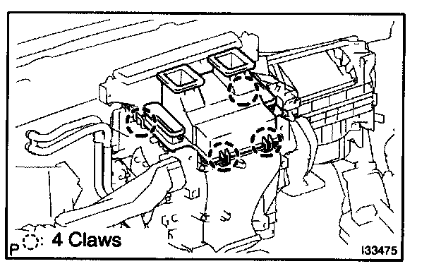
20. REMOVE HEATER TO REGISTER DUCT CENTER
a. Release the 4 claw fittings and remove the heater to register duct center.
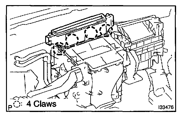
21. REMOVE DEFROSTER NOZZLE ASSY LOWER
a. Release the 4 claw fittings and remove the defroster nozzle assy lower.
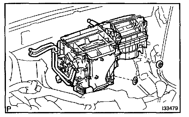
22. REMOVE AIR CONDITIONER UNIT ASSY
a. Disconnect the connectors.
b. Remove the 2 nut and airconditioner unit assy.
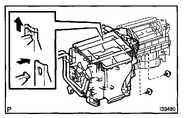
23. REMOVE AIR CONDITIONING RADIATOR ASSY
a. Remove the 2 screws and air conditioning radiator assy.
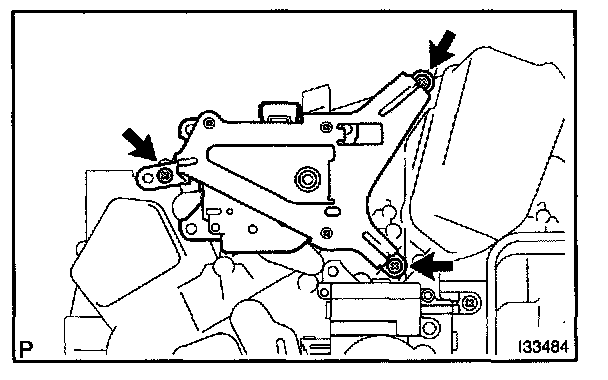
24. REMOVE MODE DAMPER SERVO SUB-ASSY
a. Remove the 3 screws and mode damper servo sub-assy.
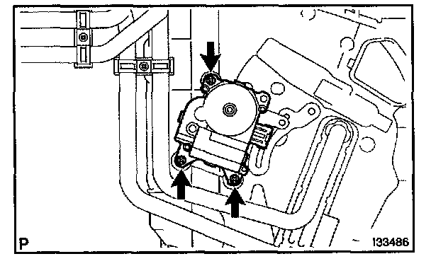
25. REMOVE DAMPER SERVO SUB-ASSY
(INDEPENDENCE TEMPERATURE CONTROL)
a. Remove the 3 screws and damper servo sub-assy.
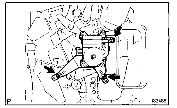
26. REMOVE DAMPER SERVO SUB-ASSY
a. Remove the 3 screws and damper servo sub-assy.
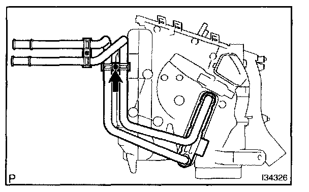
27. REMOVE HEATER RADIATOR UNIT SUB-ASSY
a. Remove the screw, clamp and heater radiator unit sub-assy.
28. REMOVE COOLER THERMISTOR NO.1
29. REMOVE COOLER COVER NO.1
30. REMOVE COOLER UNIT DRAIN HOSE NO.1
31. REMOVE AIR CONDITIONING TUBE ASSY
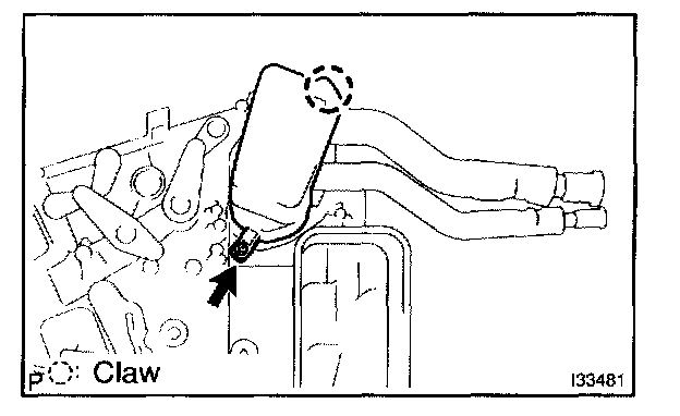
a. Remove the screw.
b. Release the claw fitting and remove the cover
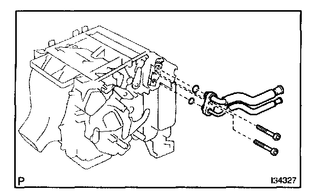
c. Using a hexagon wrench 4.0 mm (0.15 in.), remove the 2 hexagon bolts and air conditioning tube assy
d. Remove the 2 O-rings from the air conditioning tube assy.
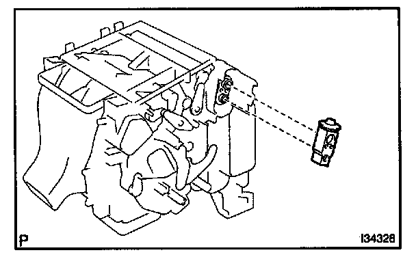
32. REMOVE COOLER EXPANSION VALVE
a. Remove the cooler expansion valve from the cooler evaporator sub-assy No.1.
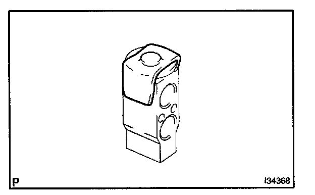
33. REMOVE COOLING UNIT PACKING NO.1
a. Remove the cooling unit packing No.1.
34. REMOVE COOLER EVAPORATOR SUB-ASSY NO.1
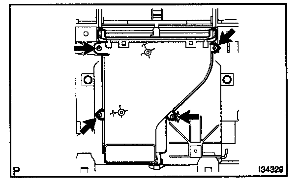
a. Remove the 4 screws and air duct sub-assy.
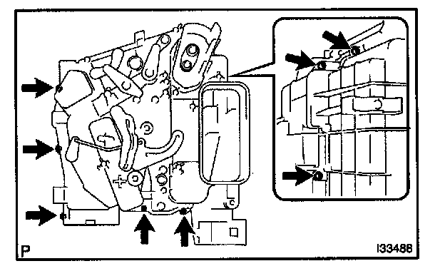
b. Remove the 8 screws and separate the heater case.
c. Remove the cooler evaporator sub-assy No.1.
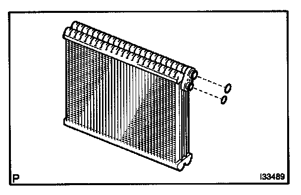
d. Remove the 2 O-rings from the cooler evaporator sub-assy No.1.
35. REMOVE COVER PLATE (EXCEPT INDEPENDENCE TEMPERATURE CONTROL)
36. INSTALL COOLER EVAPORATOR SUB-ASSY NO.1
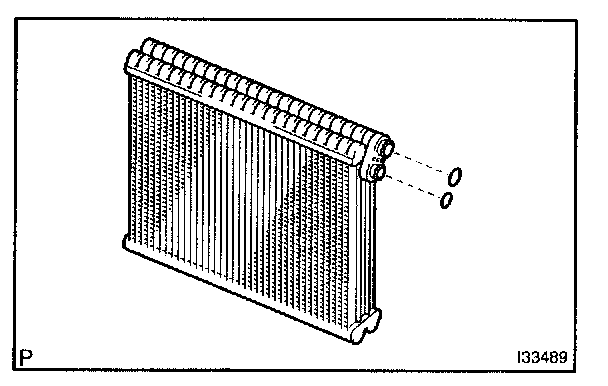
a. Sufficiently apply compressor oil to the 2 new O-rings and fitting surface of the cooler expansion valve.
Compressor oil: ND-OIL8 or equivalent
b. Install the 2 O-rings on the cooler evaporator sub-assy No.1.
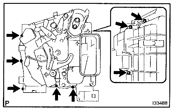
c. Install the cooler evaporator sub-assy No.1 on the heater case.
d. Install the heater case with the 8 screws.
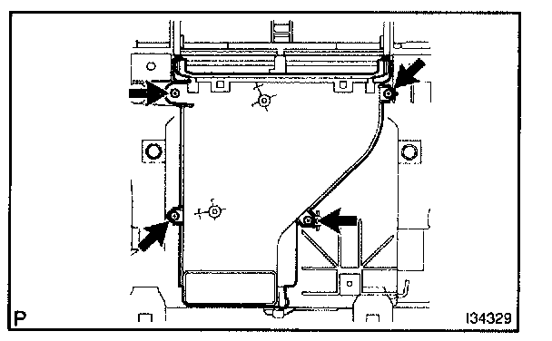
e. Install the air duct sub-assy with the 4 screws
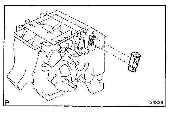
37. INSTALL COOLER EXPANSION VALVE
a. Install the cooler expansion valve from cooler evaporator sub-assy No.1.
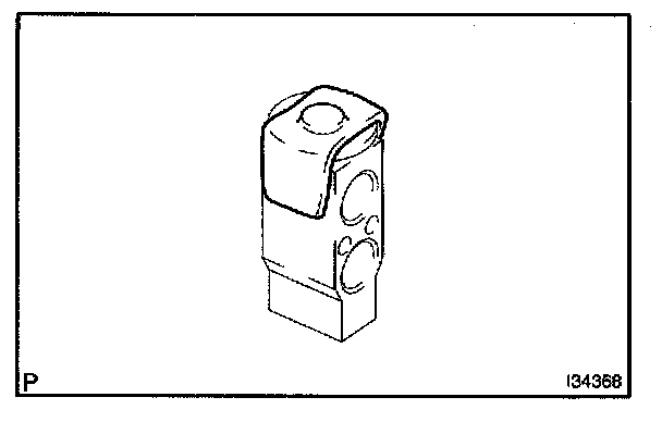
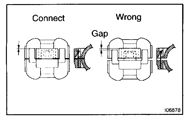
38. INSTALL COOLING UNIT PACKING NO.1
a. Install the cooling unit packing No.1.
HINT: Securely attach so that the gap in the cooling unit packing No.1 will not be mode.
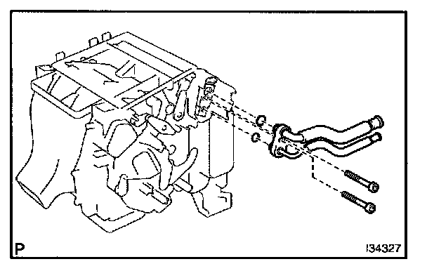
39. INSTALL AIR CONDITIONING TUBE ASSY
a. Sufficiently apply compressor oil to the 2 new 0-rings and fitting surface of the air conditioning tube assy.
Compressor oil: ND-OIL8 or equivalent
b. Install the 2 O-rings on the air conditioning tube assy.
c. Using a hexagon wrench 4.0 mm (0.15 in.), install the air conditioning tube assy with the 2 hexagon bolts.
Torque: 3.5 N.m (35 kgf.cm, 30 in.lbf)
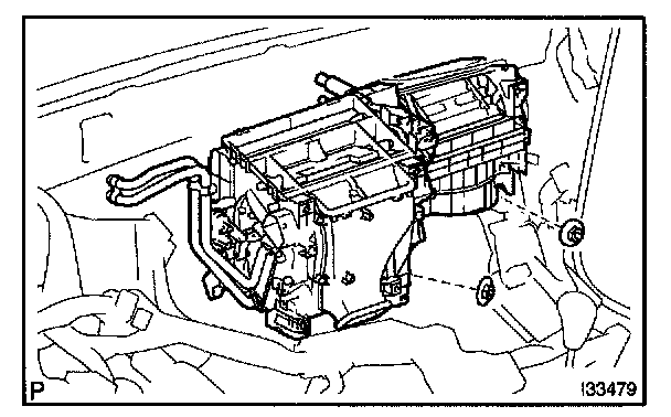
40. INSTALL AIR CONDITIONER UNIT ASSY
a. Install the air conditioner unit assy with the 2 nuts.
Torque: 5.4 N.m (55 kgf.cm, 48 in.lbf)
b. Connect the connectors.
41. INSTALL INSTRUMENT PANEL REINFORCEMENT
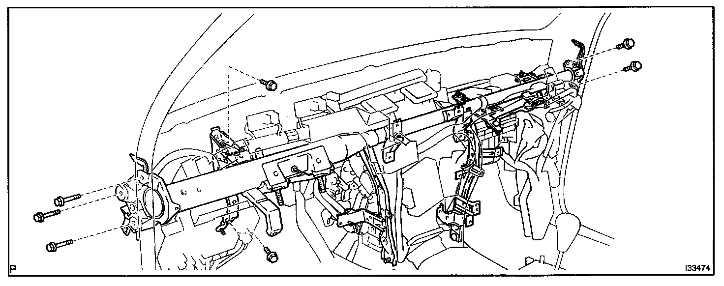
a. Install the instrument panel reinforcement with the 7 bolts.
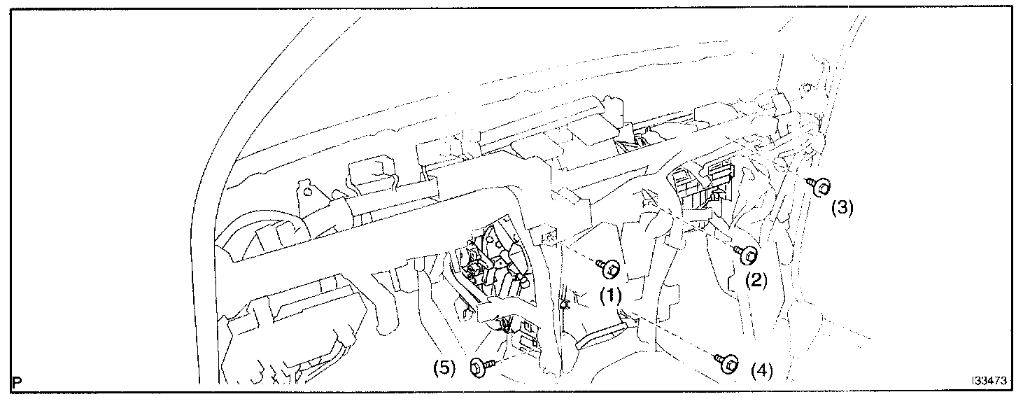
b. Install the 5 bolts.
Torque: 9.6 N.m (100 kgf.cm, 87 in.lbf)
NOTE: Tighten the bolts in following order shown in the illustration to install the air conditioner unit assy.
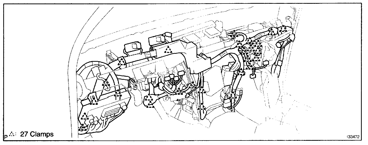
c. Install the 27 clamps.
d. Connect the connectors.
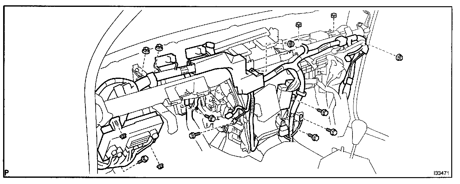
e. Install the 6 bolts and 8 nuts.
Torque: 8.3 N.m (85 kgf.cm, 73 in.lbf)
42. INSTALL STEERING COLUMN ASSY
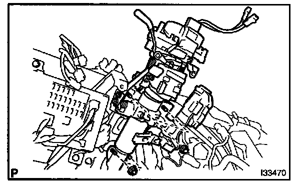
a. Install the steering column assy with the 4 nuts.
Torque: 26 N.m (265 kgf.cm, 19 in.lbf)
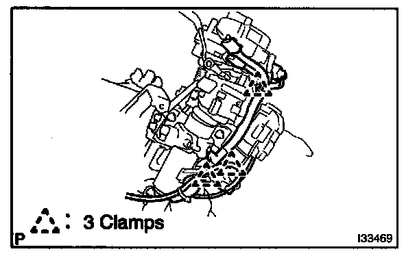
b. Install the 3 clamps and connect the connectors.
43. INSTALL INSTRUMENT PANEL SAFETY PAD SUB-ASSY
44. INSTALL COOLER REFRIGERANT LIQUID PIPE C
a. Lubricate new O-ring with compressor oil and install them on the hose.
Compressor oil: ND-OIL 8 or equivalent
b. Install the cooler refrigerant liquid pipe C and piping clamp.
HINT: After connection, check the fitting for claw of the piping clamp.
45. INSTALL COOLER REFRIGERANT SUCTION PIPE C
a. Lubricate a new O-ring with compressor oil and install them to the pipe.
Compressor oil: ND-OIL 8 or equivalent
b. Install the cooler refrigerant suction pipe C and piping clamp.
HINT: Atter connection, check the fitting for claw of the piping clamp.
46. CHARGE REFRIGERANT
SST 07110-58060 (07117-58060, 07117-58070, 07117-58080, 07117-58090, 07117-78050, 07117-88060, 07117-88070, 07117-88080)
Specified amount: 650 ± 30 g (22.92 ± 1.06 oz.)
47. WARM UP ENGINE
48. INSPECT LEAKAGE OF REFRIGERANT