Front Door: Service and Repair
DISASSEMBLY1. w/o Power window:

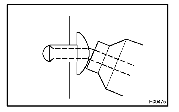
REMOVE REGULATOR HANDLE
Pull off the snap ring with a shop rag and remove the regulator handle and plate.

HINT:
- At the time of reassembly, please refer to the following item.
- With door window fully closed, install the plate and regulator handle with the snap ring in the position within ± 15 degrees as shown in the illustration.
2. REMOVE LOWER FRAME BRACKET GARNISH

Using a screwdriver, remove the lower frame bracket garnish.
HINT: Tape the screwdriver tip before use.
3. REMOVE NO. 2 DOOR INSIDE HANDLE BEZEL

Using a screwdriver, remove the No. 2 door inside handle bezel.
HINT: Tape the screwdriver tip before use.
4. REMOVE REMOTE CONTROL MIRROR SWITCH

Using a screwdriver, remove the remote control mirror switch, then disconnect the connector.
HINT: Tape the screwdriver tip before use.
5. REMOVE DOOR TRIM

a. Using a screwdriver, remove the 2 plug hole covers.
HINT: Tape the screwdriver tip before use.
b. Remove the 6 screws.
c. Insert a screwdriver between the door panel and door trim to pry the trim out.
HINT: Tape the screwdriver tip before use.
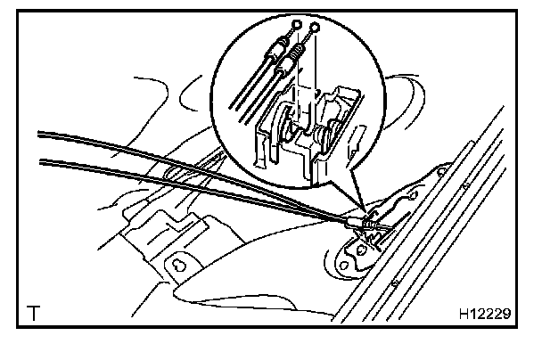
d. Pull the trim upward to remove it, then disconnect the locking cable and open cable from the door inside handle.
HINT:
- At the time of reassembly, please refer to the following items.
- Check that a ball at the end of the locking cable is pressed. (The cable should be locked.)
- Turn the locking knob of the inside handle fully to the lock side and install the locking cable.
e. Remove the screw and door inside handle from the door trim.
f. Using a screwdriver, remove the front door inner weatherstrip from the door trim.
6. REMOVE DOOR SIDE AIRBAG SENSOR
NOTE:
- If the wiring connector of the SRS is disconnected with the ignition switch in ON or ACC position, DTCs will be recorded.
- Never use SRS parts removed from another vehicle. When replacing parts, replace them with new ones.
- Never reuse the sensor involved in a collision where the SRS has deployed.
- Never repair a sensor in order to reuse it.
Disconnect the connector, then remove the 2 bolts and door side airbag sensor.
Torque: 8.0 N.m (82 kgf.cm, 71 in.lbf)
NOTE:
- At the time of reassembly, please refer to the following items.
- Make sure the sensor is installed in the specified torque.
- If the sensor has been dropped, or there are cracks, dents or any other defects are identified in the case, brackets or connector, replace the sensor. Always replace the set bolts with new ones.
- The sensor set bolts have been anti rust treated. When the sensor is removed, always replace the set bolts with new ones.
- After installation, shake the sensor to check that there is no looseness.
- The sensor is equipped with an electrical connection check mechanism. Be sure to lock this mechanism securely when connecting the connector. If not, a malfunction code may be detected by the diagnostic system.
7. REMOVE OUTSIDE REAR VIEW MIRROR
Torque: 8.3 N.m (85 kgf.cm, 74 in.lbf)
8. w/ Tweeter speaker:
REMOVE TWEETER SPEAKER
9. REMOVE SERVICE HOLE COVER
NOTE: Do not tear the cover.
HINT:
- At the time of reassembly, please refer to the following item.
- Bring out the 2 cables and wire harness through the slits of service hole cover.
10. REMOVE FRONT DOOR WEATHERSTRIP

a. Using a clip remover, remove the 4 clips.
HINT: Tape the screwdriver tip before use.
b. Using a clip remover, remove the front door weatherstrip.
HINT: Tape the screwdriver tip before use.
11. REMOVE FRONT DOOR BELT MOULDING

a. Remove the screw.
b. Using a moulding remover, remove the front door belt moulding.
12. REMOVE UPPER WINDOW STOPS

Remove the 2 bolts and 2 upper window stops.
Torque: 11 N.m (115 kgf.cm, 8 ft.lbf)
13. REMOVE DOOR GLASS

a. Close the door glass until the nuts appear in the service hole.
b. Remove the 3 nuts.
Torque: 7.8 N.m (80 kgf.cm, 69 in.lbf)
c. Take the door glass out of the panel carefully.
NOTE: Be careful not to drop the door glass.
HINT:
- At the time of reassembly, please refer to the following item.
- Insert a shop rag inside the panel to prevent the glass from being scratched.
14. REMOVE WINDOW REGULATOR
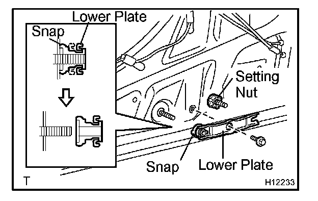
a. Remove the bolt of lower plate.
Torque: 4.9 N.m (50 kgf.cm, 43 in.lbf)
b. Unlock the snap by pulling the lower plate.
c. Remove the snap and lower plate from the stud bolt of lower bracket.
d. Remove the setting nut.
e. w/ Power window:
Disconnect the connector.
f. Remove the 5 nuts and window regulator.
Torque: 8.3 N.m (85 kgf.cm, 74 in.lbf)
15. w/ Power window:

If replacing the window regulator:
REMOVE WINDOW REGULATOR FROM MOTOR
a. Remove the 2 screws and cover plate.
b. Using needle nose pliers, remove the drum and wire guide from the motor.
NOTE: Do not use a screwdriver etc. to remove them.
16. REMOVE SPEAKER

a. Using a rivet cutter and drill, drill out the rivets and remove the speaker.
HINT: Even if flanges are taken off, continue drilling and push out remaining flangments with the drill.
b. Disconnect the connector.
c. Using a vacuum cleaner, remove the drilled rivets and the associated metallic dust from the inside of the door panel.
CAUTION: Do not touch the cut rivets and rivet cutter as they will be not.
NOTE:
- Do not jiggle the rivet cutter while cutting.
- Otherwise you may enlarge the rivet hole or damage the rivet cutter.
HINT: Do not drill the door inner hole.

HINT: At the time of reassembly, please refer to the following item. Using an air riveter, strike rivets into the door panel to install the speaker to the door panel.
NOTE: At the time of reassembly, please refer to the following item.
If the rivets are not positioned perpendicular to the assembled surface the mandrel will be bent.If the trigger is pulled in this condition, the air riveter may be also damaged.
17. REMOVE DOOR GLASS FEMALE STABILIZER

Remove the screw and door glass female stabilizer.
Torque: 4.9 N.m (50 kgf.cm, 43 in.lbf)
18. REMOVE FRONT LOWER FRAME

a. Remove the 2 screws.
b. Disengage the clamp of door wire harness from the front lower frame.
c. Remove the front lower frame through the service hole.
d. Remove the door glass run from the lower frame.
19. REMOVE FRONT DOOR NO. 2 WEATHERSTRIP

a. Using a clip remover, remove the clip.
b. Remove the front door No. 2 weatherstrip.
20. REMOVE DOOR LOCK

a. Disconnect the 2 links from the outside handle and key cylinder.
b. w/o Power door lock:
Remove the nut and 3 screws.
Torque: Nut: 5.4 N.m (55 kgf.cm, 48 in.lbf)
Screw: 4.9 N.m (50 kgf.cm, 43 in.lbf)
c. w/ Power door lock:
Disconnect the connector and remove the bolt, nut and 3 screws.
Torque: Nut: 5.4 N.m (55 kgf.cm, 48 in.lbf)
Bolt, Screw: 4.9 N.m (50 kgf.cm, 43 in.lbf)
HINT:
- At the time of reassembly, please refer to the following item.
- Apply adhesive to 3 screws.
Part No. 08833-00070, THREE BOND 1324 or equivalent
d. Remove the door lock through the service hole.
e. Remove the door lock link clamp.
HINT:
- At the time of reassembly, please refer to the following item.
- Apply MP grease to the sliding and rotating parts of the door lock.
21. REMOVE OUTSIDE HANDLE

a. Remove the 2 bolts and outside handle with key cylinder.
Torque: 5.4 N.m (55 kgf.cm, 48 in.lbf)
b. Remove the bolt and key cylinder from the outside handle.
Torque: 5.4 N.m (55 kgf.cm, 48 in.lbf)
REASSEMBLY
Reassembly is in the reverse order of disassembly.