Inspection and Replacement


INSPECTION
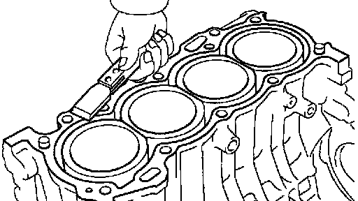
1. REMOVE GASKET MATERIAL
Using a gasket scraper, remove all the gasket material from the top surface of the cylinder block.
2. CLEAN CYLINDER BLOCK
Using a soft brush and solvent, thoroughly clean the cylinder block.
NOTICE: If the cylinder is washed at high temperatures, the cylinder liner sticks out beyond the cylinder block, so always wash the cylinder block at a temperature of 45°C (133°F) or less.

3. INSPECT TOP SURFACE OF CYLINDER BLOCK FOR FLATNESS
Using a precision straight edge and feeler gauge, measure the surface contacting the cylinder head gasket for warpage.
Maximum warpage: 0.05 mm (0.0020 inch)
If warpage is greater than maximum, replace the cylinder block.

4. INSPECT CYLINDER BORE DIAMETER
Visually check the cylinder for vertical scratches.
If deep scratches are present, replace the cylinder block.

5. INSPECT CYLINDER BORE DIAMETER
a. Using a cylinder gauge, measure the cylinder bore diameter at positions A, B and C in the thrust and axial directions.
Standard diameter:
1ZZ-FE 79.000 - 79.013 mm (3.1102 - 3.1107 inch)
2ZZ-GE 82.000 - 82.013 mm (3.2283 - 3.2289 inch)
b. Calculate the difference between the maximum diameter and the minimum diameter in the 6 measured values.
Difference limit: 0.10 mm (0.0039 inch)
If the difference is greater than limit, replace the cylinder block.

6. REMOVE CYLINDER RIDGE
If the wear is less than 0.2 mm (0.008 inch), using a ridge reamer, grind the top of the cylinder.

7. INSPECT 12 POINTED HEAD BEARING CAP SUB-ASSEMBLY BOLTS
Using vernier calipers, measure the tension portion diameter of the bolt.
Standard diameter: 7.3 - 7.5 mm (0.287 - 0.295 inch)
Minimum diameter: 7.3 mm (0.287 inch)
If the diameter is less than minimum, replace the bolt.
8. CLEAN PISTON

a. Using a gasket scraper, remove the carbon from the piston top.

b. Using a groove cleaning tool or broken ring, clean the piston ring grooves.

c. Using solvent and a brush, thoroughly clean the piston.
NOTICE: Do not use a wire brush.

9. INSPECT PISTON OIL CLEARANCE
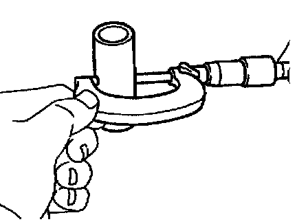
a. 1ZZ-FE: Using a micrometer, measure the piston diameter at right angles to the piston pin center line, 25.6 mm (1.008 inch) from the piston head.
b. 2ZZ-GE: Using a micrometer, measure the piston diameter at right angles to the piston pin center line, 12.0 mm (0.048 inch) from the piston bottom.
Piston diameter:
1ZZ-FE: 78.925 - 78.935 mm (3.1073 - 3.1077 inch)
2ZZ-GE: 81.975 - 81.993 mm (3.2274 - 3.2281 inch)
c. Measure the cylinder bore diameter in the thrust directions (See procedure in step 5).
d. Subtract the piston diameter measurement from the cylinder bore diameter measurement.
Standard oil clearance:
1ZZ-FE: 0.065 - 0.088 mm (0.0026 - 0.0035 inch)
2ZZ-GE: 0.007 - 0.038 mm (0.0003 - 0.0015 inch)
Maximum oil clearance: 0.10 mm (0.0039 inch)
If this oil clearance is greater than maximum, replace all the 4 pistons. If necessary, replace the cylinder block.

10. INSPECT PISTON RING GROOVE CLEARANCE
Using a feeler gauge, measure the clearance between new piston ring and the wall of the ring groove.
Ring groove clearance: 0.030 - 0.070 mm (0.0012 - 0.0028 inch)
If the clearance is not as specified, replace the piston.


11. INSPECT PISTON RING END GAP
a. Insert the piston ring into the cylinder bore.
b. Using a piston, push the piston ring a little beyond the bottom of the ring travel 110 mm (4.33 inch) from the top of the cylinder block.
c. Using a feeler gauge, measure the end gap.
Standard end gap:
No.1 0.25 - 0.35 mm (0.0098 - 0.0138 inch)
No.2 0.35 - 0.50 mm (0.0138 - 0.0197 inch)
Oil (Side rail) 0.15 - 0.40 mm (0.0059 - 0.0157 inch)
Maximum end gap:
No.1 1.05 mm (0.0413 inch)
No.2 1.20 mm (0.0472 inch)
Oil (Side rail) 1.05 mm (0.0413 inch)
If the end gap is greater than maximum, replace the piston ring.
If the end gap is greater than maximum, even with a new piston ring, replace the cylinder block.

12. INSPECT PISTON PIN FIT
At 80 - 90°C (176 - 194°F), you should be able to push the piston pin into the piston pin hole with your thumb.

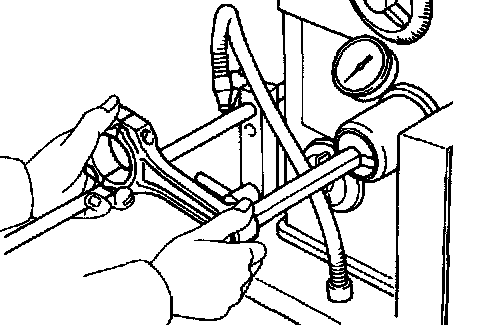
13. INSPECT CONNECTING ROD ALIGNMENT
Using a rod aligner and feeler gauge, check the connecting rod alignment.
- Check for out-of-alignment
Maximum out-of alignment: 0.05 mm (0.0020 inch) per 100 mm (3.94 inch)
If out-of alignment is greater than maximum, replace the connecting rod assembly.
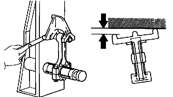
- Check for twist
Maximum twist: 0.05 mm (0.0020 inch) per 100 mm (3.94 inch)
If twist is greater than maximum, replace the connecting rod assembly.

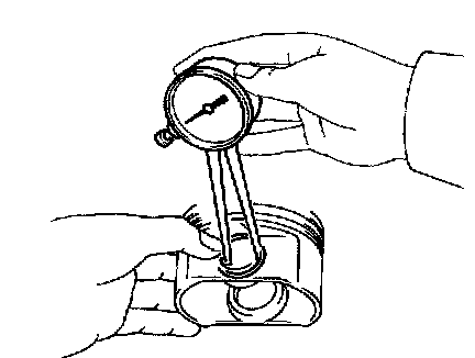
14. INSPECT PISTON PIN OIL CLEARANCE
a. Using a caliper gauge, measure the inside diameter of the connecting rod bushing.
Bushing inside diameter:
1ZZ-FE 20.012 - 20.021 mm (0.7879 - 0.7882 inch)
2ZZ-GE 20.011 - 20.023 mm (0.7878 - 0.7883 inch)
b. 2ZZ-GE: Using caliper gauge, measure the inside diameter of the piston bushing.
Bushing inside diameter: 20.013 - 20.025 mm (0.7879 - 0.7884 inch)
c. Using a micrometer, measure the piston pin diameter.
Piston pin diameter:
1ZZ-FE 20.004 - 20.013 mm (0.7876 - 0.7879 inch)
2ZZ-GE 20.004 - 20.016 mm (0.7876 - 0.7880 inch)
d. Subtract the piston pin diameter measurement from the bushing inside diameter measurement.
Standard oil clearance:
1ZZ-FE 0.005 - 0.011 mm (0.0002 - 0.0004 inch)
2ZZ-GE
Piston x Piston pin 0.005 - 0.013 mm (0.0002 - 0.0005 inch)
Piston pin x Connecting rod 0.005 - 0.009 mm (0.0002 - 0.0004 inch)
Maximum oil clearance: 0.05 mm (0.0020 inch)
If this oil clearance is greater than maximum, replace the bushing. If necessary, replace the piston and piston pin as a set.

15. INSPECT CONNECTING ROD BOLTS
Using a vernier calipers, measure the tension portion diameter of the bolt.
Standard diameter: 6.6 - 6.7 mm (0.260 - 0.264 inch)
Minimum diameter: 6.4 mm (0.252 inch)
If the diameter is less than minimum, replace the bolt.
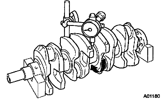
16. INSPECT CRANKSHAFT FOR CIRCLE RUNOUT
a. Place the crankshaft on V-blocks
b. Using a dial indicator, measure the circle runout, as shown in the illustration.
Maximum circle runout: 0.03 mm (0.0012 inch)
If the circle runout is greater than maximum, replace the crankshaft.
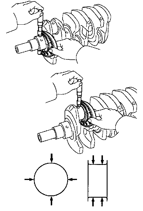
17. INSPECT MAIN JOURNALS AND CRANK PINS
a. Using a micrometer, measure the diameter of each main journal and crank pin.
Main journal diameter: 47.988 - 48.000 mm (1.8893 - 1.8898 inch)
Crank pin diameter:
1ZZ-FE: 43.992 - 44.000 mm (1.7320 - 1.7323 inch)
2ZZ-GE: 44.992 - 45.000 mm (1.7713 - 1.7717 inch)
If the diameter is not as specified, check the oil clearance.
If necessary, replace the crankshaft.
b. Check each main journal and crank pin for taper and out-of-round as shown.
Maximum taper and out-of-round: 0.02 mm (0.0008 inch)
If the taper and out-of round is greater than maximum, replace the crankshaft.
REPLACEMENT
1. REPLACE CONNECTING ROD BUSHINGS

a. Using SST and a press, press out the bushing.
SST 09222-30010
b. Align the oil hoses of a new bushing and the connecting rod.

c. Using SST and a press, press in the bushing.
SST 09222-30010
d. Using a pin hole grinder, hone the bushing to obtain the standard specified clearance between the bushing and piston pin.

e. Check the piston pin fit at normal room temperature. Coat the piston pin with engine oil, and push it into the connecting rod with your thumb.
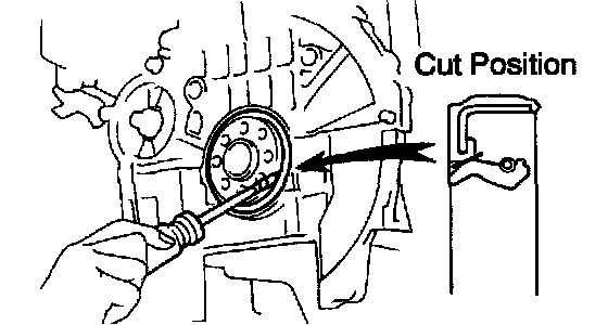
2. REPLACE CRANKSHAFT REAR OIL SEAL
If rear oil seal is installed to cylinder block.
a. Using a knife cut off the oil seal lip.
b. Using a screwdriver, pry out the oil seal.
NOTICE: Be careful not to damage the crankshaft. Tape the screw driver tip.
c. Apply MP grease to a new oil seal lip.

d. Using SST and a hammer, tap in the oil seal until its surface is flush with the rear oil seal retainer edge.
SST 09223-15030, 09950-70010 (09951-07100)