Reassembly


REASSEMBLY
HINT:
- Thoroughly clean all parts to be assembled.
- Before installing the parts, apply fresh engine oil to all sliding and rotating surfaces.
- Replace all gaskets, O-rings and oil seals with new parts.

1. ASSEMBLE PISTON AND CONNECTING ROD
a. Using a small screwdriver, install a new snap ring at one end of the piston pin hole.
HINT: Be sure that end gap of the snap ring is not aligned with the pin hole cutout portion of the piston.

b. 1ZZ-FE: Gradually treat the piston to 80 - 90°C (176 - 194°F).

c. Coat the piston pin with engine oil.
d. Align the front marks on the piston and connecting rod, and push in the piston with your thumb.

e. Using a small screwdriver, install a new snap ring on the other end of the piston pin hole.
HINT: Be sure that end gap of the snap ring is not as aligned with the pin hole cutout portion of the piston.
2. INSTALL PISTON RINGS

a. Install the oil ring expander and 2 side rails by hand.
b. Using a piston ring expander, install the 2 compression rings with the code mark facing upward.
Code mark:
1ZZ-FE: T or 2R
2ZZ-GE: T

c. Position the piston rings so that the ring ends are as shown.
NOTICE: Do not align the ring ends.

3. INSTALL CONNECTING ROD BEARINGS
a. Align the bearing claw with the groove of the connecting rod or connecting cap.
b. Install the bearings in the connecting rod and connecting rod cap.

4. INSTALL MAIN BEARINGS
HINT: Upper bearings have an oil groove and oil holes; Lower bearings do not.
a. Align the bearing claw with the claw groove of the cylinder block, and push in the 5 upper bearings.
NOTICE: Install the bearing with the oil hole in the cylinder block.

b. Align the bearing claw with the claw grove of the main bearing cap, and push in the 5 lower bearings.

5. INSTALL THRUST WASHERS
Install the 2 thrust washers under the No.3 journal position of the cylinder block with the oil grooves facing outward.
6. PLACE CRANKSHAFT ON CYLINDER BLOCK
7. PLACE BEARING CAP SUB-ASSEMBLY ON CYLINDER BLOCK

a. Remove any old packing (FIPG) material and be careful not to drop any oil on the contact surfaces of the bearing cap sub-assembly and cylinder block.
- Using a razor blade and gasket scraper, remove all the old packing (FIPG) material from the gasket surfaces and sealing grooves. thoroughly clean all components to remove all the loose material.
- Using a non-reusable solvent, clean both sealing surfaces.
b. Apply seal packing to the bearing cap sub-assembly as shown in the illustration.
Seal packing: Part No. 08826-00080 or equivalent
- Install a nozzle that has been cut to a 1 - 2 mm (0.004 - 0.08 inch) opening.
HINT: Avoid applying an excessive amount to the surface.
- Parts must be assembled within 3 minutes of application. Otherwise the material must be removed and reapplied.
- Immediately remove nozzle from the tube and reinstall cap.

c. Using a plastic-faced hammer, lightly tap the bearing cap sub-assembly to ensure a proper fit.
8. INSTALL 12 POINTED HEAD BEARING CAP SUB-ASSEMBLY BOLTS
HINT:
- The bearing cap sub-assembly bolts are tightened in 3 progressive steps (steps (b), (c) and (e).
- If any of the bearing cap sub-assembly bolts in broken or deformed, replace it.

a. Apply a light coat of engine oil on the threads and under the bearing cap sub-assembly bolts.
b. Install and uniformly tighten the 10 bearing cap sub-assembly bolts, in several passes, in the sequence shown.
Torque: 22 Nm (225 kgf-cm, 16 ft. lbs.)
c. Retighten the bearing cap subassembly bolts, in several passes, in the sequence shown.
Torque: 44 Nm (449 kgf-cm, 32 ft. lbs.)
If any of the bearing cap sub-assembly bolts does not meet the torque specification, replace the bearing cap sub assembly bolt.

d. Mark the front of the bearing cap sub-assembly bolts with paint.
e. Retighten the bearing cap sub-assembly bolts by 45° and 45° in the numerical order shown.
f. Check that the painted mark is now at a 90° angle to the front.
9. INSTALL HEXAGON HEAD BEARING CAP SUB-ASSEMBLY BOLTS
a. Install and uniformly tighten the 10 bearing cap sub-assembly bolts in several passes.
Torque:
1ZZ-FE: 18.5 Nm (189 kgf-cm, 14 ft. lbs.)
2ZZ-GE: 18 Nm (185 kgf-cm, 13 ft. lbs.)
b. Check that the crankshaft turns smoothly.
c. 2ZZ-GE Apply adhesive to 2 or 3 threads, and install the 4 screw plugs.
Adhesive: Part No. 08833-00070, THREE BOND 1324, or equivalent
Torque: 43 Nm (438 kgf-cm, 32 ft. lbs.)
10. CHECK CRANKSHAFT THRUST CLEARANCE

11. INSTALL PISTON AND CONNECTING ROD ASSEMBLES
Using a piston ring compressor, push the correctly numbered piston and connecting rod assemblies into each cylinder with the front mark of the piston facing forward.

12. PLACE CONNECTING ROD CAP ON CONNECTING ROD
a. Match the numbered connecting rod cap with the connecting rod.
b. Align the pin dowels of the connecting rod cap with the pins of the connecting rod, and install the connecting rod.

c. Check that the protrusion of the connecting rod cap is facing in the correct direction.
13. INSTALL CONNECTING ROD CAP BOLTS
HINT:
- The connecting rod cap bolts are tightened in 2 progressive steps (steps (b) and (d).
- If any of the connecting rod cap bolts is broken or deformed, replace it.

a. Apply a light coat of engine oil on the threads and under the heads of the connecting rod cap bolts.
b. Install and alternately tighten the 2 connecting rod cap bolts in several passes.
Torque:
1ZZ-FE: 20 Nm (204 kgf-cm, 15 ft. lbs.)
2ZZ-GE: 30 Nm (306 kgf-cm, 22 ft. lbs.)
If any of the connecting rod cap bolts does not meet the torque specification, replace the connecting rod cap bolts.

c. Mark the front of the connecting cap bolts with paint.
d. Retighten the cap bolts by 90° as shown.
e. Check that the painted mark is now at a 90° angle to the front.
f. Check that the crankshaft turns smoothly.
14. CHECK CONNECTING ROD THRUST CLEARANCE
15. INSTALL REAR CRANKSHAFT OIL SEAL
HINT: Wipe seal packing away from the contact surface of the cylinder block assembly and oil seal.

16. 1ZZ-FE: INSTALL OIL STRAINER
Install a new gasket and the oil strainer with the 2 nuts and bolt.
Torque: 9.0 Nm (92 kgf-cm, 80 inch lbs.)

17. 2ZZ-GE: INSTALL OIL PAN BAFFLE AND OIL STRAINER
a. Install the oil pan baffle with the 4 bolts and 2 nuts.
Torque: 9.0 Nm (92 kgf-cm, 80 inch lbs.)
b. Install a new gasket and oil strainer with the 2 nuts and bolt.
Torque: 9.0 Nm (92 kgf-cm, 80 inch lbs.)

18. INSTALL OIL PAN
a. Remove any old packing (FIPG) material and be careful not to drop any oil on the contact surface of the main bearing cap and oil pan.
- Using a razor blade and gasket scraper, remove all the old packing (FIPG) mat-trial from the gasket surfaces and sealing grooves.
- Thoroughly clean all components to remove all the loose material.
- Using a non-residue solvent, clean both sealing surfaces.
NOTICE: Do not use a solvent which will affect the painted surfaces.
b. Apply seal packing to the oil pan as shown in the illustration.
Seal packing: Part No. 08826-00080 or equivalent
- Install a nozzle that has been cut to a 4 - 5 mm (0.16 - 0.20 inch) opening.
HINT: Avoid applying an excessive amount to the surface.
- Parts must be assembled within 3 minutes of application. Otherwise the material must be removed and reapplied.
- Immediately remove nozzle from the tube and reinstall cap.

c. 1ZZ-FE: Install the oil pan with the 14 bolts and 2 nuts. Uniformly tighten the bolts and nuts in several passes.
d. 2ZZ-GE: Install the oil pan with the 12 bolts and 4 nuts. Uniformly tighten the bolts and nuts in several passes.
Torque: 9.0 Nm (92 kgf-cm, 80 inch lbs.)
19. INSTALL OIL FILTER UNION
Torque: 30 Nm (306 kgf-cm, 21 ft. lbs.)
20. INSTALL OIL FILTER
21. INSTALL OIL PUMP

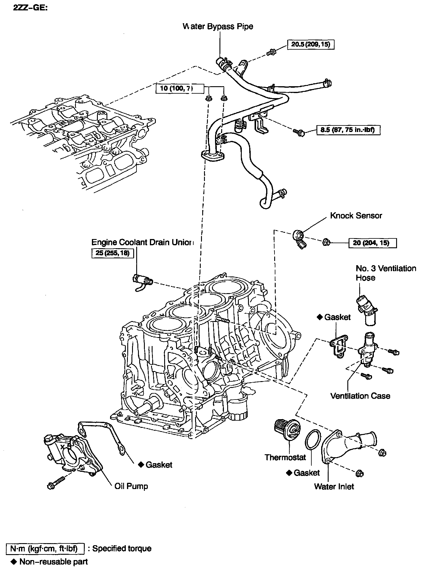
22. INSTALL ENGINE COOLANT DRAIN UNION
a. Apply adhesive to 2 or 3 threads.
Adhesive: Part No. 08833-00080, THREE BOND 1344, LOCTITE 242 or equivalent
b. Install the drain union.
Torque:
1ZZ-FE 20 Nm (200 kgf-cm, 14 ft. lbs.)
2ZZ-GE 25 Nm (255 kgf-cm, 18 ft. lbs.)
HINT: After applying the specified torque, rotate the drain union clockwise until its drain port is facing downward.
23. INSTALL KNOCK SENSOR
Torque:
1ZZ-FE 44 Nm (450 kgf-cm, 33ft. lbs.)
2ZZ-GE 20 Nm (204 kgf-cm,15 ft. lbs.)

24. 2ZZ-GE: INSTALL VENTILATION CASE
a. Install a new gasket and ventilation case with the 3 bolts.
Torque: 8.5 Nm (87 kgf-cm, 75 inch lbs.)
b. Install the No. 3 ventilation hose and connect the clip.
25. INSTALL THERMOSTAT

26. INSTALL WATER BYPASS PIPE
Torque:
1ZZ-FE 9.0 Nm (92 kgf-cm, 80 inch lbs.)
2ZZ-GE
Bolt 8.5 Nm (87 kgf-cm, 75 inch lbs.)
Nut 10 Nm (100 kgf-cm, 7 ft. lbs.)
27. 1ZZ-FE: INSTALL OIL DIPSTICK AND GUIDE
a. Install a new O-ring on the dipstick guide.
b. Apply soapy water on the O-ring.
c. Connect the dipstick guide end to the main bearing cap.
d. Install the dipstick guide with the bolt.
Torque: 11 Nm (113 kgf-cm, 8 ft. lbs.)
28. INSTALL CYLINDER HEAD
29. INSTALL ENGINE WIRE
30. INSTALL TIMING SPROCKETS AND TIMING CHAIN
31. REMOVE ENGINE STAND

32. M/T: INSTALL FLYWHEEL
HINT: The flywheel bolts are tightened in 2 progressive steps, (a) and (c).
a. Install and uniformly tighten the 8 mounting bolts, in several passes, in the sequence shown.
Torque: 49 Nm (500 kgf-cm, 36ft. lbs.)

b. Mark the flywheel bolt with paint.
c. Retighten the flywheel bolts by an additional 90°.
d. Check that the painted mark in now at a 90° angle to (b).
33. A/T: INSTALL DRIVE PLATE

a. Install the front spacer, drive plate and rear plate on the crankshaft.
b. Apply adhesive to 2 or 3 threads of the mounting bolt end.
Adhesive: Part No. 08833-00070, THREE BOND or equivalent

c. Install and uniformly tighten the 8 mounting bolts, in several passes, in the sequence shown.
Torque: 88 Nm (897 kgf-cm, 65 ft. lbs.)