Disassembly
Part 1 Of 6:

Part 2 Of 6:

Part 3 Of 6:

Part 4 Of 6:

Part 5 Of 6:

Part 6 Of 6:
DISASSEMBLY

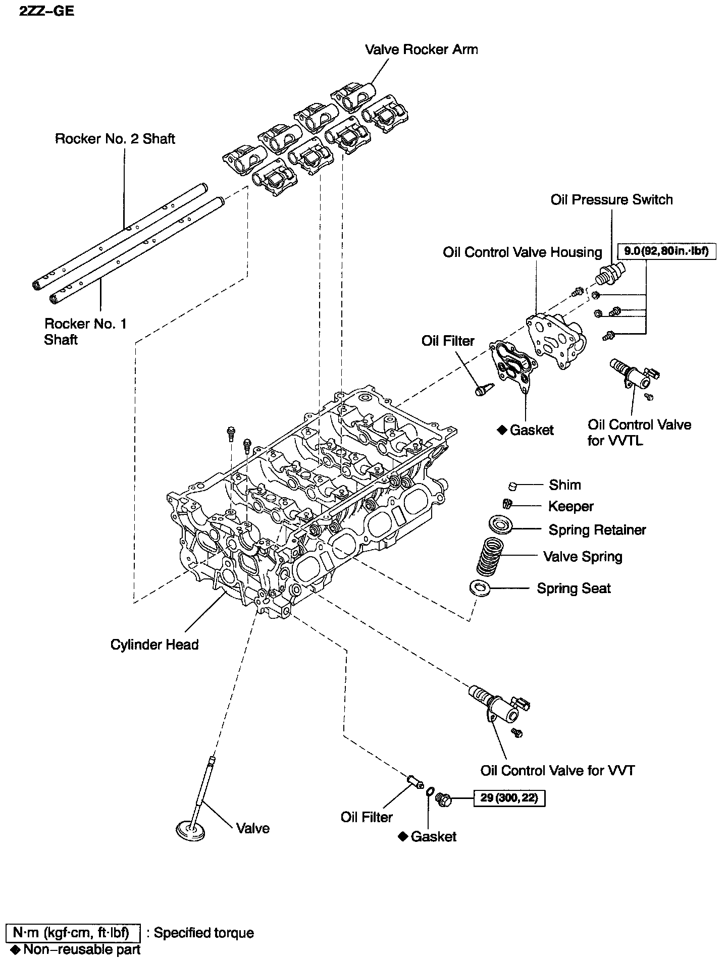
1. REMOVE OIL CONTROL VALVE for VVT
Remove the bolt and cam timing oil control valve.
2. REMOVE OIL CONTROL VALVE FILTER
Remove the bolt, gasket and oil control valve filter.

3. REMOVE OIL CONTROL VALVE HOUSING
a. Remove the bolt and oil control valve for VVTL.
b. Using SST, remove the oil pressure switch.
SST 09816-30010
c. Remove the 3 bolts, 2 nuts, oil control valve housing and gasket.
d. Remove the oil control valve filter.
4. 2ZZ-GE: REMOVE VALVE ROCKER ARM
a. Remove the 2 bolts, rocker No.1 and No. 2 shafts.
b. Remove the 8 valve rocker arm.
HINT: Arrange the rocker arms in the correct order.
5. REMOVE VALVE LIFTERS
HINT: Arrange the valve lifters in the correct order.

6. REMOVE VALVES
a. Using SST, compress the valve spring and remove the 2 keepers.
SST 09202-70020 (09202-00020)
b. Remove the spring retainer.
c. Remove the valve spring.
d. Remove the valve.

e. Using needle-nose pliers, remove the oil seal.

f. Using compressed air and magnetic finger, remove the spring seat by blowing air.
HINT: Arrange the valves, valve springs, spring seats, and spring retainers in the correct order.
INSPECTION
1. CLEAN TOP SURFACES OF PISTONS AND CYLINDER BLOCK

a. Turn the crankshaft, and bring each piston to top dead center (TDC). Using a gasket scraper, remove all the carbon from the piston surface.

b. Using a gasket scraper, remove all the gasket material from the cylinder block surface.
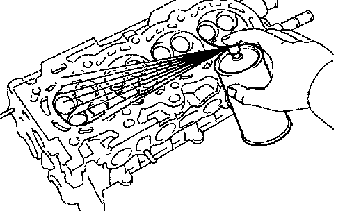
c. Using compressed air, blow carbon and oil from the bolt holes.
CAUTION: Protect your eyes when using high pressure compressed air.

2. REMOVE GASKET MATERIAL
Using a gasket scraper, remove all the gasket material from the cylinder block contact surface.
NOTICE: Be careful not to scratch the cylinder block contact surface

3. CLEAN COMBUSTION CHAMBERS
Using a wire brush, remove all the carbon from the combustion chambers.
NOTICE: Be careful not to scratch the cylinder block contact surface
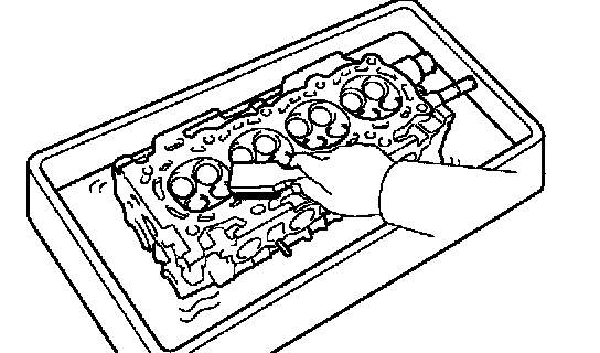
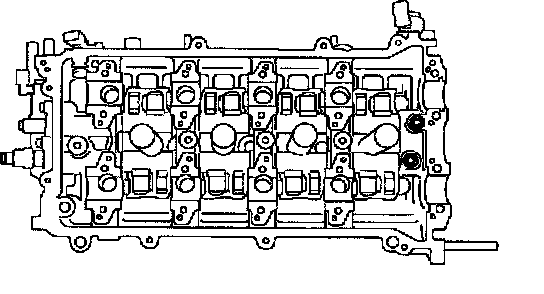
4. CLEAN CYLINDER HEAD
Using a soft brush and solvent, thoroughly clean the cylinder heat .

5. CLEAN VALVE GUIDE BUSHINGS
Using a valve guide bushing brush and solvent, clean all the guide bushings.

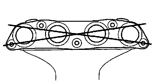
6. INSPECT FOR FLATNESS
Using a precision straight edge and feeler gauge, measure the surface contacting the cylinder block and the manifolds for warpage.
Maximum warpage: 0.05 mm (0.0020 inch)
If warpage is greater than maximum, replace the cylinder head.
7. INSPECT FOR CRACKS
Using a dye penetrate, check the combustion chamber, intake ports, exhaust ports and cylinder block surface for cracks. If cracked, replace the cylinder head.

8. CLEAN VALVES
a. Using a gasket scraper, chip off any carbon from the valve head.
b. Using a wire brush, thoroughly clean the valve.
9. INSPECT VALVE STEMS AND GUIDE BUSHINGS

a. Using a caliper gauge, measure the inside diameter of the guide bushing.
Bushing inside diameter:
1ZZ-FE 5.510 - 5.530 mm (0.2169 - 0.2177 inch)
2ZZ-GE 5.500 - 5.518 mm (0.2165 - 0.2172 inch)

b. Using a micrometer, measure the diameter of the valve stem
Valve stem diameter:
1ZZ-FE
Intake 5.470 - 5.485 mm (0.2154 - 0.2159 inch)
Exhaust 5.465 - 5.480 mm (0.2152 - 0.2157 inch)
2ZGE
Intake 5.460 - 5.475 mm (0.21496 - 0.21555 inch)
Exhaust 5.445 - 5.470 mm (0.21437 - 0.21535 inch)
c. Subtract the valve stem diameter measurement from the guide bushing inside diameter measurement.
Standard oil clearance:
1ZZ-FE
Intake 0.025 - 0.060 mm (0.0010 - 0.0024 inch)
Exhaust 0.030 - 0.065 mm (0.0012 - 0.0026 inch)
2ZZ-GE
Intake 0.025 - 0.058 mm (0.00098 - 0.00228 inch)
Exhaust 0.030 - 0.063 mm (0.00118 - 0.00248 inch)
Maximum oil clearance:
1ZZ-FE
Intake 0.08 mm (0.0031 inch)
Exhaust 0.10 mm (0.0039 inch)
2ZZ-GE 0.10 mm (0.0039 inch)
If the clearance is greater than maximum, replace the valve and guide bushing.

10. INSPECT VALVES
a. Check the valve is ground to the correct valve face angle.
Valve face angle: 44.5°
b. Check that the surface of the valve for wear.
If the valve face is worn, replace the valve.
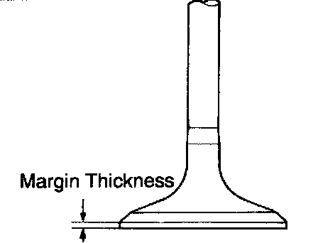
c. Check the valve head margin thickness.
Standard margin thickness: 1.0 mm (0.039 inch)
Minimum margin thickness: 0.7 mm (0.028 inch)
If the margin thickness is less than minimum, replace the valve.

d. Check the valve overall length.
Standard overall length:
1ZZ-FE
Intake 88.65 mm (3.4902 inch)
Exhaust 88.69 mm (3.4917 inch)
2ZZ-GE
Intake 111.3 mm (4.382 inch)
Exhaust 111.7 mm (4.398 inch)
Minimum overall length:
1ZZ-FE
Intake 88.35 mm (3.4783 inch)
Exhaust 88.39 mm (3.4799 inch)
2ZZ-GE
Intake 110.9 mm (4.366 inch)
Exhaust 111.3 mm (4.382 inch)
If the overall length is less than minimum, replace the valve.
e. Check the surface of the valve stem tip for wear.
If the valve stem tip is worn, replace the valve.
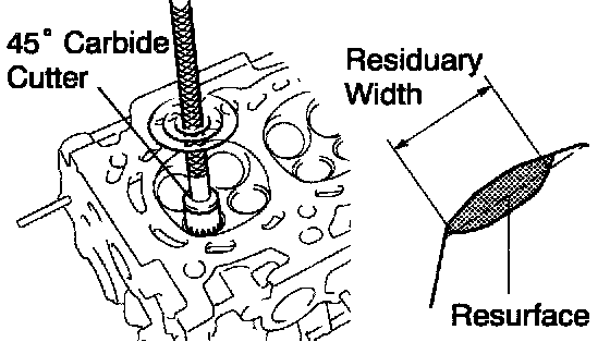
11. INSPECT AND CLEAN VALVE SEATS
a. Using a 45° carbide cutter, resurface the valve seats.
Remove only enough metal to clean the seats.

b. After resurfacing the valve seat 45°, measure the residuary width of the valve seat 45°.
Minimum residuary length:
Intake 3.3 mm (0.130 inch)
Exhaust 3.2 mm (0.126 inch)
If the valve seat 45° residuary width less then minimum, replace the cylinder head.
c. Check the valve seating position.
Apply a light coat of prussian blue (or white lead) to the valve face. Lightly press the valve against the seat. Do not rotate valve.
d. Check the valve face and seat for the following:
- If blue appears 360° around the face, the valve is concentric. If not, replace the valve.
- If blue appears 360° around the valve seat, the guide and face are concentric. If not, resurface the seat.
- Check that the seat contact is in the middle of the valve face with the following width: 1.0 - 1.4 mm (0.039 - 0.055 inch)
If no it, correct the valve seats as follows:

1. If the seating is too high on the valve face, use 30° and 45° cutters to correct the seat.

2. If the seating is too low on the valve face, use 75° and 45° cutters to correct the seat.

e. Hand-lap the valve and valve seat with an abrasive compound.
f. After hand-lapping, clean the valve and valve seat.

12. INSPECT VALVE SPRINGS
a. Using a steel square, measure the deviation of the valve spring.
Maximum deviation: 1.6 mm (0.063 inch)
Maximum angle (reference): 2°
If the deviation is greater than maximum, replace the valve spring.

b. Using vernier calipers, measure the free length of the valve spring.
Free length:
1ZZ-FE 45.90 mm (1.8070 inch)
2ZZ-GE
Intake 46.4 mm (1.830 inch)
Exhaust 46.5 mm (1.831 inch)

c. Using a spring tester, measure the tension of the valve spring at the specified installed length.
Installed tension:
1ZZ-FE
139.6 - 154.4 N (14.2 - 15.8 kgf, 31.3 - 34.8 lbs.) at 33.6 mm (1.323 inch)
2ZZ-GE
Intake
220.2 - 243.8 N (22.5 - 24.7 kgf, 49.6 - 55.5 lbs.) at 38.5 mm (1.516 inch)
Exhaust
208.2 - 229.8 N (21.2 - 23.4 kgf, 47.6 - 52.6 lbs.) at 38.5 mm (1.516 inch)
Maximum working tension:
1ZZ-FE
244.9 - 276.1 N (25.5 - 28.1 kgf, 56.2 - 61.9 lbs.) at 24.6 mm (0.969 inch)
2ZZ-GE
Intake
533 - 589 N (54.4 - 60.1 kgf, 119.9 - 132.5 lbs.) at 27.3 mm (1.075 inch)
Exhaust
495.5 - 548.5 N (50.5 - 55.9 kgf, 111.3 - 123.2 lbs.) at 28.5 mm (1.122 inch)
If the installed tension is not as specified, replace the valve spring

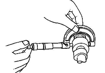
13. INSPECT CAMSHAFT FOR RUNOUT
a. Place the camshaft on V-blocks.
b. Using a dial indicator, measure the circle runout at the center journal.
Maximum circle runout: 0.03 mm (0.0012 inch)
If the circle runout is greater than maximum, replace the camshaft.

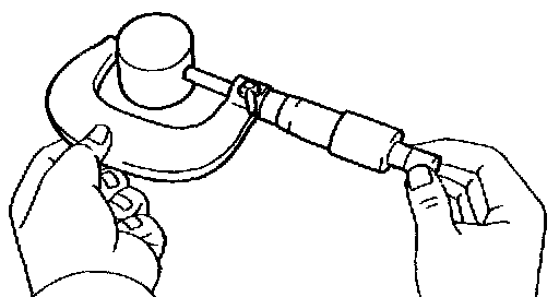
14. INSPECT CAM LOBES
Using a micrometer, measure the cam lobe height
Standard cam lobe height:
1ZZ-FE:
Intake 44.333 - 44.433 mm (1.7454 - 1.7493 inch)
Exhaust 43.761 - 43.861 mm (1.7229 - 1.7268 inch)
2ZZ-GE:
INTAKE
No.1 40.607 - 40.707 mm (1.59586 - 1.59979 inch)
No. 2 38.769 - 38.869 mm (1.52362 - 1.52755 inch)
2ZZ-GE:
EXHAUST
No.1 40.019 - 40.119 mm (1.57275 - 1.57668 inch)
No. 2 38.863 - 38.963 mm (1.52732 - 1.53125 inch)
Minimum cam lobe height:
1ZZ-FE:
Intake 44.18 mm (1.7394 inch)
Exhaust 43.61 mm (1.7169 inch)
2ZZ-GE:
Intake
No.1 40.45 mm (1.5925 inch)
No.2 38.61 mm (1.5201 inch)
Exhaust
No.1 39.86 mm (1.5693)
No.2 38.71 mm (1.5240)
If the cam lobe height is less than minimum, replace the camshaft.
15. INSPECT CAMSHAFT JOURNALS
Using a micrometer, measure the journal diameter.
1ZZ-FE:
No.1 journal diameter: 34.449 - 34.465 mm (1.3563 - 1.3569 inch)
Others journal diameter: 22.949 - 22.965 mm (0.9035 - 0.9041 inch)
2ZZ-GE:
No.1 journal diameter: 34.449 - 34.465 mm (1.35626 - 1.35689 inch)
Other journal diameter: 27.949 - 27.965 mm (1.10035 - 1.10098 inch)
If the journal diameter is not as specified, check the oil clearance.
16. INSPECT CAMSHAFT JOURNAL CLEARANCE

a. Clean the bearing caps and camshaft journals.
b. Place the camshafts on the cylinder head.
c. Lay a strip of Plastigage across each of the camshaft journal.

d. Install the bearing caps.
Torque:
1ZZ-FE:
No.1 23 Nm (235 kgf-cm, 17 ft. lbs.)
No.3 13 Nm (133 kgf-cm, 10 ft. lbs.)
2ZZ-GE: 18.5 Nm (189 kgf-cm, 14 ft. lbs.)
NOTICE: Do not turn the camshaft.
e. Remove the bearing caps.

f. Measure the plastigage at its widest point.
1ZZ-FE:
Standard oil clearance: 0.035 - 0.072 mm (0.0014 - 0.0028 inch)
Maximum oil clearance: 0.10 mm (0.0039 inch)
2ZZ-GE:
Standard oil clearance:
No.1 journal 0.035 - 0.076 mm (0.00138 - 0.00299 inch)
Other journal 0.035 - 0.072 mm (0.00138 - 0.00283 inch)
Maximum oil clearance: 0.10 mm (0.039 inch)
If the oil clearance is greater than maximum, replace the camshaft. If necessary, replace the bearing caps and cylinder head as a set.
g. Completely remove the Plastigage.
h. Remove the camshafts.

17. INSPECT CAMSHAFT THRUST CLEARANCE
a. Install the camshafts.
b. Using a dial indicator, measure the thrust clearance while moving the camshaft back and forth.
1ZZ-FE:
Standard thrust clearance: 0.040 - 0.095 mm (0.0016 - 0.0037 inch)
Maximum thrust clearance: 0.11 mm (0.0043 inch)
2ZZ-GE:
Standard thrust clearance: 0.04 - 0.14 mm (0.0016 - 0.0055 inch)
Maximum thrust clearance: 0.15 mm (0.0059 inch)
If the thrust clearance is greater than maximum, replace the camshaft. If necessary, replace the bearing caps and cylinder head as a set.
c. Remove the camshafts.

18. INSPECT VALVE TIMING CONTROLLER ASSEMBLY
a. Apply vinyl tape to all the ports except the one indicated by the arrow in the illustration.
NOTICE: Do not apply tape in the range from the tip of the camshaft to 13 mm from that tip.
Install the valve timing controller assembly.
Torque: 47 Nm (480 kgf-cm, 35 ft. lbs.)
NOTICE: Do not push valve timing controller assembly to the camshaft forcibly when installing it.
c. Check that the valve timing controller assembly will not turn.

d. Wind tape around the tip of the air gun and apply air of approximately 100 kPa (1 kgf/cm2, 14 psi) to the port of the camshaft.
NOTICE: When the oil splashes, wipe it off with a shop rag and the like.
HINT: Perform this in order to release the lock pin for the maximum delay/angle locking.
e. Under the condition of (d), turn the valve timing controller assembly to the advance angel side (the arrow marked direction in the illustration) with your hand.
Standard: Must turn
HINT: Depending on the air pressure, the valve timing controller assembly will turn to the advance angle side without applying force by hand. Also, under the condition that the pressure can be hardly applied because of the air leakage from the port, there may be the case that the lock pin could be hardly released.
f. Except the position where the lock pin meets at the maximum delay angle, let the valve timing controller assembly turn back and forth and check the movable range and that there is no disturbance.
Standard: Movable smoothly in the range about 30°
g. Turn the valve timing controller assembly with your hand and lock it at the maximum delay angel position.

19. 1ZZ-FE: INSPECT VALVE LIFTERS AND LIFTER BORES
a. Using a caliper gauge, measure the lifter bore diameter of the cylinder head.
Lifter bore diameter: 31.000 - 31.025 mm (1.2205 - 1.2215 inch)
b. Using a micrometer, measure the lifter diameter.
Lifter diameter: 30.966 - 30.976 mm (1.2191 - 1.2195 inch)
c. Subtract the lifter diameter measurement from the lifter bore diameter measurement.
Standard oil clearance: 0.024 - 0.059 mm (0.0009 - 0.0023 inch)
Maximum oil clearance: 0.079 mm (0.0031 inch)
If the oil clearance is greater than maximum, replace the lifter.
If necessary, replace the cylinder head.

20. INSPECT INTAKE MANIFOLD
Using a precision straight edge and feeler gauge, measure the surface contacting the cylinder head for warpage.
Maximum warpage: 0.10 mm (0.0039 inch)
If warpage is greater than maximum, replace the manifold.
21. INSPECT EXHAUST MANIFOLD
Using a precision straight edge and feeler gauge, measure the surface contacting the cylinder head for warpage.
Maximum warpage: 0.70 mm (0.0276 inch)
If weepage is greater than maximum, replace the manifold.
22. INSPECT CYLINDER HEAD BOLTS
Standard outside diameter: 9.0 - 9.2 mm (0.354 - 0.362 inch)
Minimum outside diameter: 9.0 mm (0.354 inch)
If the outer diameter is less than minimum, replace the bolt.
REPLACEMENT
REPLACE VALVE GUIDE BUSHINGS

a. Gradually heat the cylinder head to 110 - 130°C (230 - 266°F).

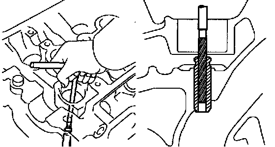
b. Using SST and a hammer, tap out the guide bushing.
SST 09201-01055, 09950-70010 (09951-07100)

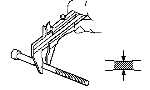
c. Using a caliper gauge, measure the bushing bore diameter of the cylinder head.
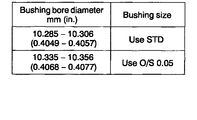
d. 1ZZ-FE: Select the new guide bushing (STD or O/S 0.05).
If the bushing bore diameter of the cylinder head is greater than 10.306 mm (0.4057 inch), machine the bushing bore to the following dimension:
10.335 - 10.356 mm (0.4068 - 0.4077 inch)
If the bushing bore diameter of the cylinder head is greater than 10.356 mm (0.4077 inch), replace the cylinder head.
e. 1ZZ-FE: Gradually heat the cylinder head to 80 - 100°C (176 - 212°F).

f. 2ZZ-GE: Select the new guide bushing (STD or O/S 0.05).
If the bushing bore diameter of the cylinder head is greater than 10.606 mm (0.4136 inch), machine the bushing bore to the following dimension: 10.538 - 10.556 mm (0.4149 - 0.4156 inch)
If the a bushing bore diameter of the cylinder head is greater than 10.556 mm (0.4156 inch), replace the cylinder head.
g. 2ZZ-GE: Gradually heat the cylinder head to 110 - 130°C (230 - 266°F).

h. Using SST and a hammer, tap in a new guide bushing to the specified protrusion height.
SST 09201-01055, 09950-70010 (09951-07100)
Protrusion height:
1ZZ-FE 8.7 - 9.1 mm (0.342 - 0.358 inch)
2ZZ-GE 15.3 - 15.7 mm (0.602 - 0.618 inch)
i. Using a sharp 5.5 mm reamer, ream the guide bushing to obtain the standard specified clearance between the guide bushing and valve stem.