Installation
Part 1 Of 6:

Part 2 Of 6:

Part 3 Of 6:

Part 4 Of 6:

Part 5 Of 6:

Part 6 Of 6:
INSTALLATION
HINT:
- Thoroughly clean all parts to be assembled.
- Before installing the parts, apply fresh engine oil to all sliding and rotating surfaces.
- Replace all gaskets and oil seals with new ones.
1. PLACE CYLINDER HEAD ON CYLINDER BLOCK
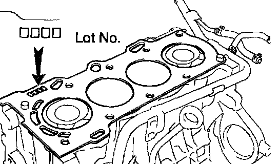
a. Place a new cylinder head gasket on the cylinder block surface with the Lot No. stamp upward.
NOTICE: Be careful of the installation direction.
b. Place the cylinder head quietly in order not to damage the gasket with the bottom part of the head.
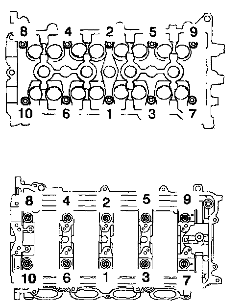
2. INSTALL CYLINDER HEAD BOLTS
HINT:
- The cylinder head bolts are tightened in 2 progressive steps (steps (b) and (d).
- If any cylinder head bolt is broken or deformed, replace it.
a. Apply a light coat if engine oil on the threads and under the heads of the cylinder head bolts.
b. Using a 10 mm bi-hexagon wrench, install and uniformly tighten the 10 cylinder head bolts and plate washers, in several passes, in the sequence shown.
Torque:
1ZZ-FE: 49 Nm (500 kgf-cm, 36 ft. lbs.)
2ZZ-GE: 35 Nm (375 kgf-cm, 26 ft. lbs.)
If any one of the cylinder head bolts does not meet the torque specification, replace the cylinder head bolt.

c. Mark the front of the cylinder head bolt with paint.
d. 1ZZ-FE: Retighten the cylinder head bolts 90° in the numerical order shown.
e. 2ZZ-GE: Retighten the cylinder head bolts 180° in the numerical order shown.
f. 1ZZ-FE: Check that the paint mark is now at a 90° angle to the front.
g. 2ZZ-GE: Check that the paint mark is now at a 180° angle to the front.

h. Install the bolt holding the water bypass pipe to the cylinder head.
Torque: 9.0 Nm (92 kgf-cm, 80 inch lbs.)
Connect the upper radiator hose to the water hose unions.
i. Connect the heater hose to the water hose unions.
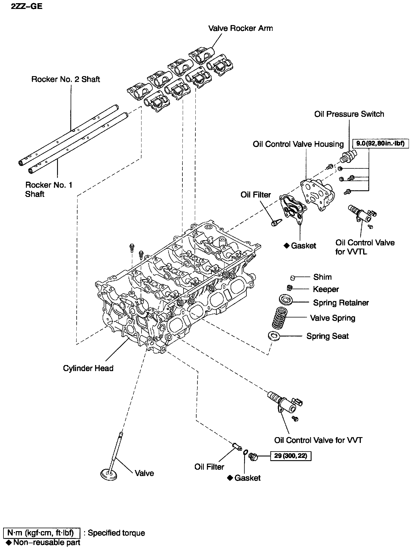
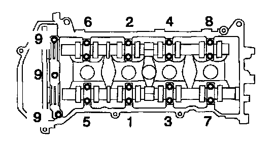
3. INSTALL CAMSHAFTS

a. Place the 2 camshafts on the cylinder head with the No. 1 cam lobes facing as shown the illustration.

b. Install the bearing caps in their proper locations.
HINT:
- 1ZZ-FE: No. 3 camshaft bearing cap has a number and front mark.
- 2Z2-GE: No. 2, No.3 camshaft bearing cap has a number and front mark.
c. Apply a light coat of engine oil on the threads and under the heads of the bearing cap bolts.
d. 1ZZ-FE: Install and uniformly tighten the 19 bearing cap bolts.
After tightening the No. 1 camshaft bearing cap, tighten then in several passes, in the sequence shown.
Torque:
No. 1. 23 Nm (235 kgf-cm, 17 ft. lbs.)
No. 3. 13 Nm (133 kgf-cm, 10 ft. lbs.)
HINT:
Bearing cap No. 1 - Illustration No. 9
Bearing cap No. 3 - Illustrations 1 to 8

e. 2ZZ-GE: Install and uniformly tighten the 20 bearing cap bolts. After tightening the No. 1 camshaft bearing cap, tighten then in several passes, in the sequence shown.
Torque: 18.5 Nm (189 kgf-cm, 14 ft. lbs.)
4. CHECK AND ADJUST VALVE CLEARANCE
5. INSTALL CAMSHAFT TIMING SPROCKETS AND VALVE TIMING CONTROLLER ASSEMBLY
6. INSTALL OIL FILTER CAP
7. INSTALL GROMMET AND PCV VALVE
8. INSTALL ECT SENSOR
9. INSTALL CAMSHAFT POSITION SENSOR

10. 1ZZ-FE: INSTALL INTAKE MANIFOLD
a. Install a new gasket, the intake manifold with the 4 bolts and 2 nuts.
Torque: 18.5 Nm (189 kgf-cm, 14 ft. lbs.)
Connect the brake booster vacuum hose.
Connect the EVAP hose for ORVR.

11. 2ZZ-GE: INSTALL INTAKE MANIFOLD
a. Install the intake manifold insulator to the cylinder block.
b. Install a new gasket, the intake manifold with the 4 bolts and 2 nuts.
Torque:
A: 27 Nm (275 kgf-cm, 20 ft. lbs.)
B: 46 Nm (469 kgf-cm, 34 ft. lbs.)
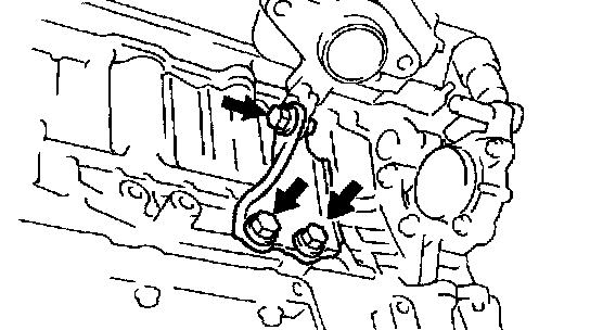
c. Install the stay with the 2 bolts and nut.
Torque: 24 Nm (245 kgf-cm, 18 ft. lbs.)
d. Install the oil dipstick and guide with the bolt.
Torque: 25 Nm (255 kgf-cm, 18 ft. lbs.)
e. Connect the brake booster vacuum hose.
f. Connect the EVAP hose for ORVR.

12. 1ZZ-FE: CONNECT ENGINE WIRE TO CYLINDER HEAD
a. Connect the 2 clamps of engine wire to the intake manifold.
b. Connect the 2 ground cables.
c. Connect the oil control valve for VVT connector.
d. Connect the camshaft position sensor connector.
e. Connect the ECT sensor connector.

13. 2ZZ-GE: CONNECT ENGINE WIRE TO CYLINDER HEAD
a. Install the intake manifold insulator No. 2.
b. Connect the 2 ground cables.
c. Connect the oil pressure switch connector.
d. Connect the oil control valve for VVT connector.
e. Connect the oil control valve for VVTL connector.
f. Connect the camshaft position sensor connector.
g. Connect the ECT sensor connector.
h. Install the accelerator cable bracket with the 2 bolts.
14. INSTALL INJECTORS
15. INSTALL THROTTLE BODY
16. INSTAL PCV HOSES
17. INSTALL SPARK PLUGS
18. INSTALL IGNITION COIL

19. 1ZZ-FE: INSTALL EXHAUST MANIFOLD
a. Install the lower heat insulator with the 3 bolts.
Torque: 12 Nm (123 kgf-cm, 9 ft. lbs.)
b. Install a new gasket, and the exhaust manifold with the nuts. Uniformly tighten the nuts in several passes.
Torque: 37 Nm (377 kgf-cm, 27 ft. lbs.)
c. Install the upper heat insulator with the 6 bolts.
Torque: 12 Nm (123 kgf-cm, 9 ft. lbs.l
d. Install the exhaust manifold stay with the 3 bolts.
Torque: 49 Nm (500 kgf-cm, 37 ft. lbs.)

20. 2ZZ-GE: INSTALL EXHAUST MANIFOLD
a. Install the lower heat insulator with the 4 bolts.
Torque: 20 Nm (204 kgf-cm, 15 ft. lbs.)
b. Install the exhaust manifold with the 3 bolts and 2 nuts.
Torque: 50 Nm (510 kgf-cm, 37 ft. lbs.)
c. Install the upper heat insulator with the 5 bolts.
Torque: 20 Nm (204 kgf-cm, 15 ft. lbs.)
c. Install the exhaust manifold stay withe 4 bolts.
Torque: 50 Nm (510 kgf-cm, 37 ft. lbs.)
21. INSTALL EXHAUST PIPE
22. INSTALL GENERATOR AND DRIVE BELT
23. CONNECT ACCELERATOR CABLE
24. INSTALL AIR CLEANER ASSEMBLY
25. INSTALL ECU BOX
26. INSTALL BATTERY
27. FILL WITH ENGINE COOLANT
28. START ENGINE AND CHECK FOR LEAKS
29. RECHECK ENGINE COOLANT LEVEL AND OIL LEVEL