Reassembly
Part 1 Of 6:

Part 2 Of 6:

Part 3 Of 6:

Part 4 Of 6:

Part 5 Of 6:

Part 6 Of 6:
REASSEMBLY
HINT:
- Thoroughly clean all parts to be assembled.
- Before installing the parts, apply fresh engine oil to all sliding and rotating surfaces.
- Replace oil seals with new ones.

1. INSTALL WATER HOSE UNIONS
HINT: When using a new cylinder head, water hose unions must be installed.
a. Mark the standard position away from the edge, onto the water hose union.

b. Apply adhesive to the water hose union hole of the cylinder head.
Adhesive: Part No.08833-00070, THREE BOND 1324 or equivalent

c. Using a press, press in a new water hose union until there is protruding from the cylinder head.
Standard protrusion:
A 29 mm (1.14 inch)
B 66.5 mm (2.618 inch)
C 24 mm (0.95 inch)
D 69.8 mm (2.630 inch)
NOTICE: Avoid pressing a new water hose union in too far by measuring the amount of protrusion while pressing.
2. INSTALL VALVES

a. Using SST, push in a new oil seal.
SST 09201-41020

HINT:
- 1ZZ-FE: The intake valve oil seal is light brown and the exhaust valve oil seal is gray.
- 2ZZ-GE: The intake valve oil seal is black and the exhaust valve oil seal is green.
NOTICE: Pay much attention assembling the oil seal for intake and exhaust. Assembling the wrong one may cause a failure.
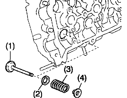
b. Install the valve (1), spring (2), valve spring (3), and spring retainer (4).

c. Using SST, compress the valve spring and place the 2 keepers around the valve stem.
SST 09202-70020 (09202-00020)

d. Using a plastic-faced hammer and the valve stem (not in use) tip wound with vinyl tape, lightly tap the valve stem tip to ensure a proper fit.
NOTICE: Be careful not to damage the valve stem tip.
3. INSTALL VALVE LIFTERS
a. Install the valve lifter.
b. 4. Check that the valve lifter rotates smoothly by hand.
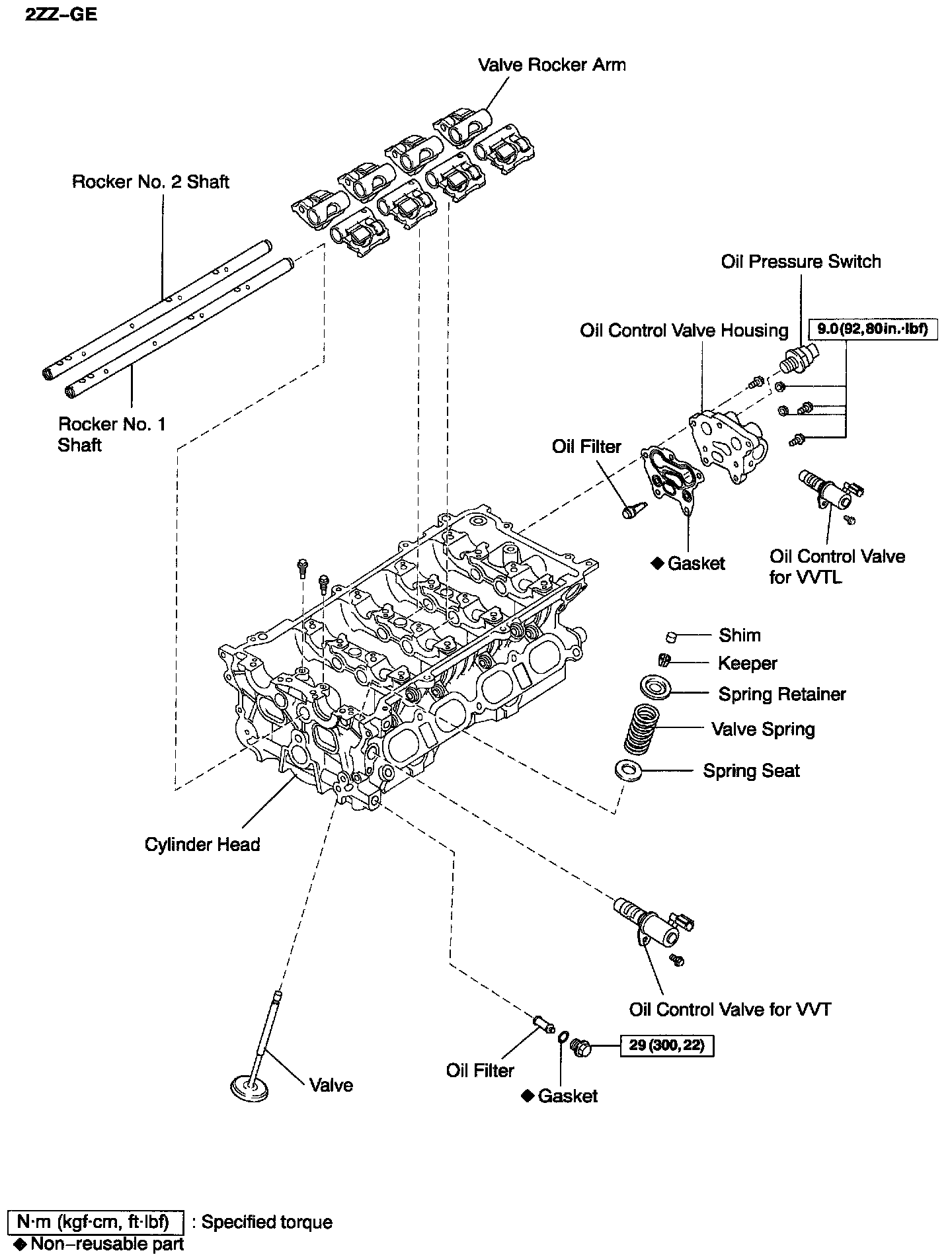
4. 2ZZ-GE: INSTALL VALVE ROCKER ARM
a. Set the 8 valve rocker arms.
b. Install the rocker No. 1 and No. 2 shaft with the 2 bolts.
Torque: 7.5 Nm (76 kgf-cm, 66 inch lbs.)

HINT:
- Position the slit of the locker shaft in the direction shown in the illustration.
- Align the locker shaft end with the cylinder head end.
5. 2ZZ-GE: INSTALL OIL CONTROL VALVE HOUSING
a. Install the oil control valve filter.
b. Install the gasket and oil control valve housing with the 3 bolts and 2 nuts.
Torque: 9.0 Nm (92 kgf-cm, 80 inch lbs.)
c. Apply adhesive to 2 or 3 threads of the oil pressure switch.
Adhesive: Part No. 08833-00080, THREE BOND 1344, LOCTITE 242 or equivalent
d. Using SST, install the oil pressure switch.
SST 09816-30010
Torque: 13 Nm (130 kgf-cm, 9 ft. lbs.)
e. Install the oil control valve for VVTL with the bolt.

6. INSTALL CONTROL VALVE for VVT
Install the oil control valve for VVT with the bolt.
7. INSTALL OIL CONTROL VALVE FILTER
Install the oil control valve filter and new gasket with the bolt.
Torque: 29 Nm (300 kgf-cm, 22 ft. lbs.)