Oil Pump Assembly Overhaul
Part 1 Of 4:

Part 2 Of 4:

Part 3 Of 4:

Part 4 Of 4:

DISASSEMBLY
1. REMOVE RELIEF VALVE
Remove the plug, spring and relief valve.
2. REMOVE DRIVE AND DRIVEN ROTORS
a. 1ZZ-FE: Remove the 3 screws, pump body cover, drive and driven rotors.
b. 2ZZ-GE: Remove the 5 screws, pump body cover, drive and driven rotors.
INSPECTION

1. INSPECT OIL JET
Check the oil jet for damage or clogging. If necessary, replace the oil pump assembly.

2. INSPECT RELIEF VALVE
Coat the valve with engine oil and check that it falls smoothly into the valve hole by its own weight.
If it does not, replace the relief valve. If necessary, replace the oil pump assembly.
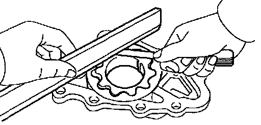
3. INSPECT ROTOR SIDE CLEARANCE
Using a feeler gauge and precision straight edge, measure the clearance between the rotors and precision straight edge.
Standard side clearance:
1ZZ-FE 0.025 - 0.071 mm (0.00098 - 0.00280 inch)
2ZZ-GE 0.030 - 0.080 mm (0.00118 - 0.00314 inch)
Maximum side clearance:
1ZZ-FE 0.071 mm (0.00280 inch)
2ZZ-GE 0.160 mm (0.00630 inch)
If the side clearance is greater than maximum, replace the rotors as a set. If necessary, replace the oil pump assembly.

4. INSPECT ROTOR BODY CLEARANCE
Using a feeler gauge, measure the clearance between the driven rotor and body.
Standard body clearance:
1ZZ-FE 0.260 - 0.325 mm (0.01024 - 0.01280 inch)
2ZZ-GE 0.125 - 0.180 mm (0.00492 - 0.00709 inch)
Maximum body clearance: 0.325 mm (0.01280 inch)
If the body clearance is greater than maximum, replace the rotors as a set. If necessary, replace the oil pump assembly.

5. INSPECT ROTOR TIP CLEARANCE
Using a feeler gauge, measure the clearance between the drive and driven rotor tips.
Standard tip clearance:
1ZZ-FE 0.040 - 0.160 mm (0.00157 - 0.00630 inch)
2ZZ-GE 0.060 - 0.180 mm (0.00236 - 0.00709 inch)
Maximum tip clearance:
1ZZ-FE 0.16 mm (0.00630 inch)
2ZZ-GE 0.35 mm (0.01378 inch)
If the tip clearance is greater than maximum, replace the rotors as a set.
REASSEMBLY
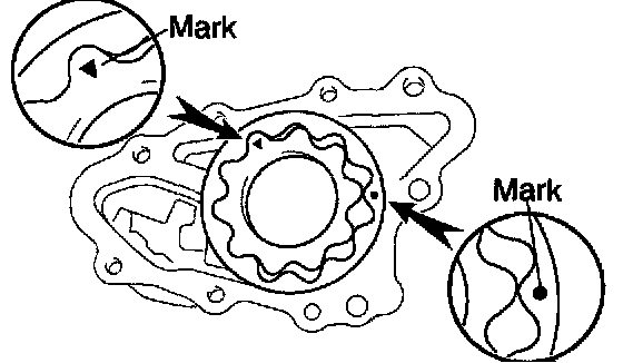
1. INSTALL DRIVE AND DRIVEN ROTORS
a. Place the drive and driven rotors into pump body with the marks facing the pump body cover side.
b. 1ZZ-FE: Install the pump body cover with the 3 screws.
Torque: 10.5 Nm (107 kgf-cm, 8 ft. lbs.)
c. 2ZZ-GE Install the pump body cover with the 5 screws.
Torque: 10.5 Nm (107 kgf-cm, 8ft. lbs.)
2. INSTALL RELIEF VALVE
Insert the relief valve and spring into the pump body hole, and install the plug.
Torque:
1ZZ-FE: 37 Nm (375 kgf-cm, 27 ft. lbs.)
2ZZ-GE: 49 Nm (500 kgf-cm, 36 ft. lbs.)