SRS Connectors
SRS CONNECTORS
HINT: SRS connectors are located as shown in the following illustration.
a. All connectors in the SRS are colored in yellow to distinguish them from other connectors. Connectors having special functions and specifically designed for the SRS are used in the locations shown to ensure high reliability. These connectors use durable gold-plated terminals.
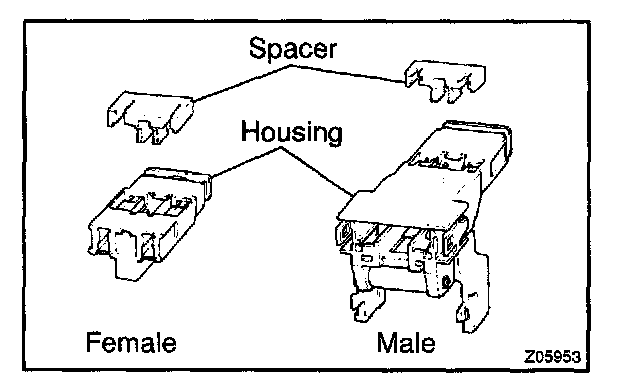
1. Terminal Twin-Lock Mechanism
Each connector has a two-piece component consisting of a housing and a spacer. This design enables the terminal to be locked securely by two locking devices (the retainer and the lance) to prevent terminals from coming out.
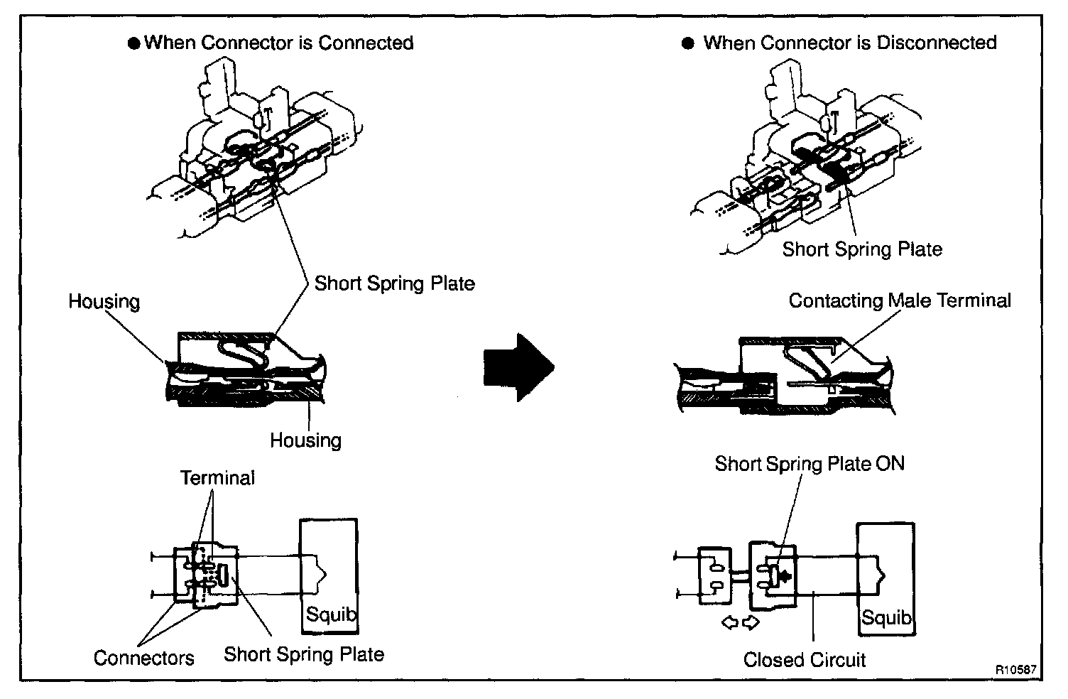
2. Airbag Activation Prevention Mechanism
Each connector contains a short spring plate. When the connector is disconnected, the short spring plate automatically connects positive (+) terminal and negative (-) terminal of the squib.
HINT: The type of connector is shown in the diagram.
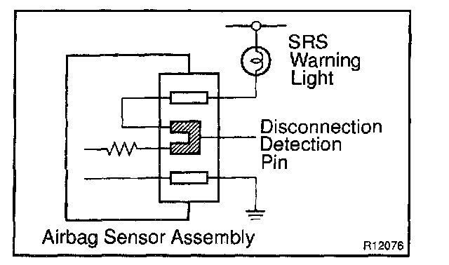

3. Electrical Connection Check Mechanism
This mechanism electrically checks that connectors are connected correctly and completely. The electrical connection check mechanism is designed so that the disconnection detection pin connects with the diagnosis terminals when the connector housing lock is locked.
HINT: The illustration shows connectors "1", "2" and "3" in step 11.
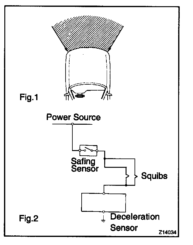
b. When the vehicle is involved in a frontal collision in the hatched area (Fig. 1) and the shock is larger than the predetermined level, the SRS is activated automatically. A safing sensor is designed to go on at a smaller deceleration rate than the airbag sensor. As illustrated in Fig. 2, ignition is caused when current flows to the squib, which happens when a safing sensor and the deceleration sensor go on simultaneously. When a deceleration force acts on the sensors, 2 squibs in the driver airbag and front passenger airbag ignite and generate gas. The gas discharging into the driver airbag and front passenger airbag rapidly increases the pressure inside the bags, breaking open the steering wheel pad and instrument panel. Bag inflation then ends, and the bags deflate as the gas is discharged through discharge holes at the bag's rear or side.