Service Data
REMOVAL

1. REMOVE TRANSAXLE FROM ENGINE
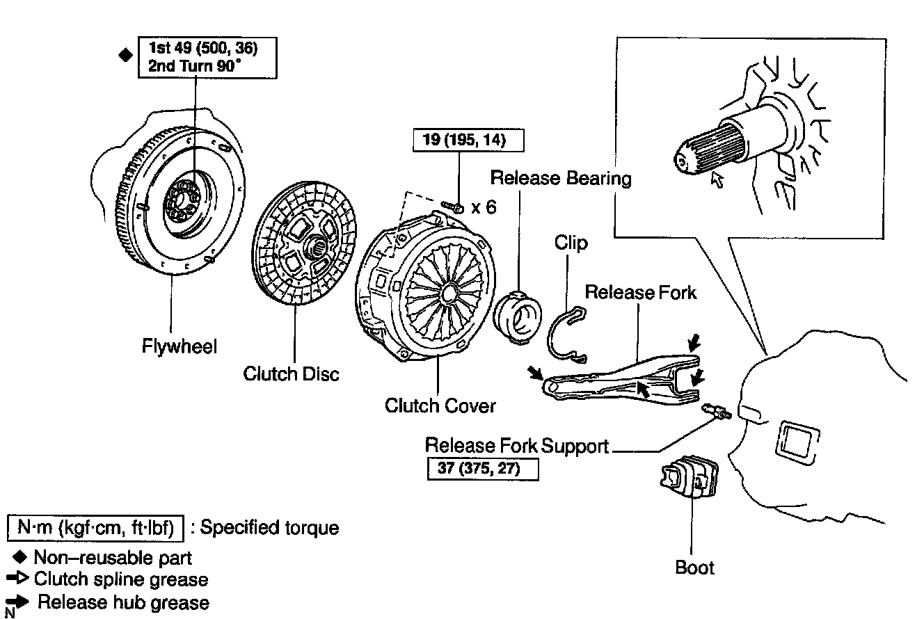
2. REMOVE CLUTCH COVER AND DISC
a. Align the matchmark on the clutch cover with the one on the flywheel.
b. Loosen each set bolt one turn at a time until spring tension is released.
c. Remove the set bolts, and pull off the clutch cover with the clutch disc.
NOTICE: Do not drop the clutch disc.

3. REMOVE RELEASE BEARING AND FORK FROM TRANSAXLE
Remove the release bearing with the fork together and then separate them.
4. REMOVE RELEASE FORK SUPPORT AND BOOT
INSPECTION
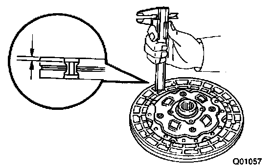
1. INSPECT CLUTCH DISC FOR WEAR OR DAMAGE
Using vernier calipers, measure the rivet head depth.
Minimum rivet depth: 0.3 mm (0.012 inch)
If necessary, replace the clutch disc.
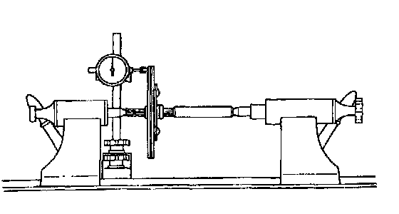
2. INSPECT CLUTCH DISC RUNOUT
Using a dial indicator, check the disc runout.
Maximum runout: 0.8 mm (0.031 inch)
If necessary, replace the clutch disc runout.

3. INSPECT FLYWHEEL RUNOUT
Using a dial indicator, check the flywheel runout.
Maximum runout: 0.1 mm (0.004 inch)
If necessary, replace the flywheel.
HINT: The flywheel bolts are tightened in 2 progressive steps, (1) and (3).

1. Install and uniformly tighten the - mounting bolts, in several passes, in the sequence shown.
Torque: 49 Nm (500 kgf-cm, 36 ft. lbs.)

2. Mark the flywheel bolt with paint.
3. Retighten the flywheel bolts by an additional 90°.
4. Check that the painted mark in now at a 90° angle to (2).

4. INSPECT DIAPHRAGM SPRING FOR WEAR
Using vernier calipers, measure the diaphragm spring for depth and width of wear.
Maximum:
A (Depth): 0.5 mm (0.020 inch)
B (Width): 6.0 mm (0.236 inch)
If necessary, replace the clutch cover.

5. INSPECT RELEASE BEARING
Turn the bearing by hand while applying force in the axial direction.
HINT: The bearing is permanently lubricated and requires no cleaning or lubrication. If necessary, replace the release bearing.
INSTALLATION
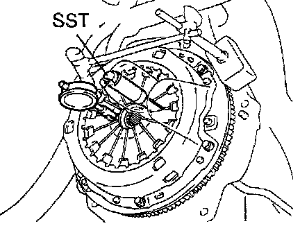
1. INSTALL CLUTCH DISC AND CLUTCH COVER ON FLYWHEEL

a. Insert SST in the clutch disc, then insert them in the flywheel.
SST 09301-00210
HINT: Take care not to insert clutch disc in the wrong direction.

b. Align the matchmarks on the clutch cover and flywheel.
c. Following the procedures shown in the illustration, tighten the 6 bolts in the order starting the bolt locating near the knock pin on the top.
Torque: 19 Nm (195 kgf-cm, 14 ft. lbs.)
HINT:
^ Following the order in the illustration, tighten the bolts at a time evenly.
^ Move SST up and down, right and left lightly, after checking that the disc is in the center, tighten the bolts.
2. CHECK DIAPHRAGM SPRING TIP ALIGNMENT
Using a dial indicator with roller instrument, check the diaphragm spring tip alignment.
Maximum non-alignment: 0.5 mm (0.020 inch)
If alignment is not as specified, using SST, adjust the diaphragm spring tip alignment.
SST 09333-00013
3. INSTALL BOOT AND RELEASE FORK SUPPORT TO TRANSAXLE;
Torque: 37 Nm (375 kgf-cm, 27 ft. lbs.)

4. APPLY RELEASE HUB GREASE
Apply release hub grease to the release fork and hub contact, release fork and push rod contact and release fork pivot points. Sealant:
Part No. 08887-01806, RELEASE HUB GREASE or equivalent
5. APPLY CLUTCH SPRING GREASE
Apply clutch spline grease to the input shaft spline.
Sealant:
Part No. 08887-01706, CLUTCH SPLINE GREASE or equivalent
6. INSTALL RELEASE BEARING AND FORK TO TRANSAXLE
Install the bearing to the release fork, and then install them to the transaxle.
7. INSTALL TRANSAXLE TO ENGINE