Disassembly and Assembly
Part 1 Of 2:

Part 2 Of 2:

DISASSEMBLY

1. REMOVE COLUMN UPPER BRACKET AND COLUMN UPPER CLAMP
a. Using a centering punch, mark the center of the 2 tapered-head bolts.
b. Using as 3 - 4 mm (0.12 - 0.16 inch) drill, drill into the 2 bolts.
c. Using a screw extractor, remove the 2 bolts, column upper bracket and column upper clamp.
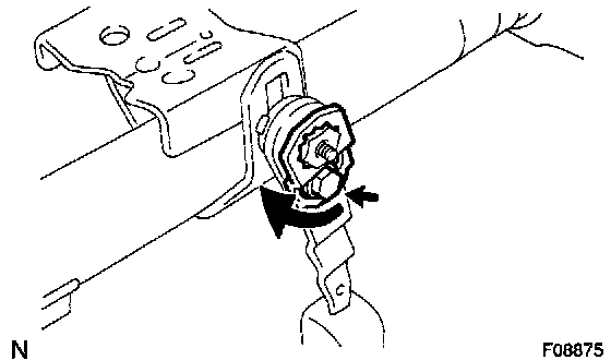
2. REMOVE TILT STEERING SUPPORT
Remove the bolt and tilt steering support.
3. REMOVE BRACKET SPACER AND 2 NO. 1 SUPPORT COLLARS

a. Using an extension bar and a hammer, tap out the bracket spacer.

b. Using a screwdriver, remove the 2 No. 1 support collars.
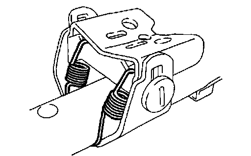
4. REMOVE TILT LEVER AND BREAK AWAY BRACKET
a. Remove the tilt spring.
b. Remove the No. 2 tilt lever lock bolt and No. 1 support reinforce.
HINT: This bolt is left-handed one.

c. Remove the adjusting nut, tilt lever, stopper, tilt lever lock bolt and break away bracket.
HINT: This nut is left-handed one.
d. Remove the No. 2 support collar from the break away bracket.
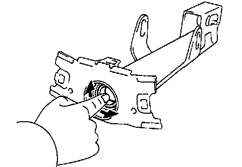
5. REMOVE MAIN SHAFT BUSHING
Using a screwdriver and hammer, tap out the main shaft bushing.
6. REMOVE MAIN SHAFT ASSEMBLY
a. Using a snap ring expander, remove the snap ring on the upper side.
b. Remove the main shaft assembly.
c. Using a snap ring expander, remove the snap ring on the lower side.
INSPECTION
1. INSPECT STEERING LOCK OPERATION
Check that the steering lock mechanism operates properly.
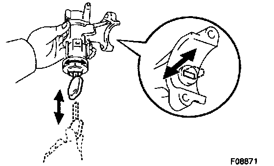
2. IF NECESSARY, REPLACE KEY CYLINDER
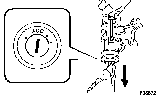
a. Place the ignition key at the ACC position.
b. Push down the stop pin with a screwdriver, and pull out the cylinder.
c. Install a new cylinder.
HINT: Make sure the key is at the ACC position.
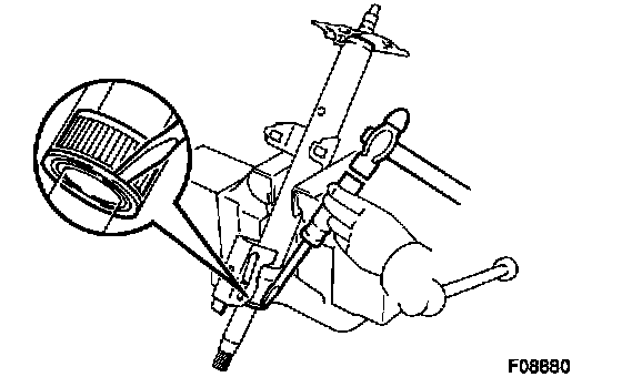
3. INSPECT IGNITION SWITCH
4. IF NECESSARY, REPLACE IGNITION SWITCH
a. Remove the 2 screws and ignition switch from the column upper bracket.
b. Install a new ignition switch with the 2 screws.
5. INSPECT KEY UNLOCK WARNING SWITCH
6. IF NECESSARY, REPLACE KEY UNLOCK WARNING SWITCH
a. Slide the key unlock warning switch out of the column upper bracket.
b. Slide a new key unlock warning switch in the column upper bracket.
7. INSPECT BEARING
Check the bearing rotation condition and check for abnormal noise.
If the bearing is worn or damaged, replace the column tube.
REASSEMBLY
NOTICE: When using a vise, do not overtighten it.
1. COAT PARTS INDICATED BY ARROWS WITH MOLYBDENUM DISULFIDE LITHIUM BASE GREASE
2. INSTALL MAIN SHAFT ASSEMBLY
a. Using a snap ring expander, install a new snap ring on the lower side.
b. Install the main shaft assembly.
c. Using a snap ring expander, install a new snap ring on the upper side.
3. INSTALL MAIN SHAFT BUSHING
a. Coat a new bushing with molybdenum disulfide lithium base grease.

b. Using SST and a hammer, tap in the main shaft bushing. SST 09608-04031
4. INSTALL BREAK AWAY BRACKET AND TILT LEVER
a. Install the No. 2 support collar to the break away bracket.
b. Install the break away bracket, tilt lever lock bolt, stopper and tilt lever.
HINT: Align the holes in the column tube with the projections of the tilt lever lock bolt and stopper.

c. Install the adjusting nut by rotating it counterclockwise in the specified torque so that the locking load (load applied to when a knob is operated) of the tilt lever will be 38 - 82 N (3.9 - 8.4 kgf, 8.5 - 18.4 lbs.).
Torque: 9 Nm - 14 Nm (90 kgf-cm - 145 kgf-cm, 80 inch lbs. - 10 ft. lbs.)

d. Install the No. 1 support reinforce with the No. 2 tilt lever lock bolt by turning it counterclockwise.
Torque: 5.4 Nm (55 kgf-cm, 48 inch lbs.)
HINT: Align the No. 1 support reinforce with the nut to eliminate looseness by turning the No. 1 support reinforce counterclockwise a little, then torque the No. 2 tilt lever lock bolt.
e. Install the tilt spring.
5. INSTALL 2 NO. 1 SUPPORT COLLARS AND BRACKET SPACER
a. Install 2 new No. 1 support collars.
HINT: Install the white support collar to the RH side, black support collar to the LH side.
b. Using an extension bar and a hammer, drive in the bracket spacer.
6. INSTALL TILT STEERING SUPPORT Install the tilt steering support with the bolt.
Torque: 15 Nm (155 kgf-cm, 11 ft. lbs.)
NOTICE: Make sure that the tilt steering support is installed facing in the correct direction.

7. INSTALL COLUMN UPPER BRACKET AND COLUMN UPPER CLAMP
a. Install the column upper bracket and column upper clamp with 2 new tapered-head bolts.
b. Tighten the 2 tapered-head bolts until the bolt heads break off.