Removal and Installation
Part 1 Of 2:

Part 2 Of 2:

REMOVAL
1. REMOVE STEERING WHEEL PAD
NOTICE: If the airbag connector is disconnected with the ignition switch at ON, DTCs will be recorded.
a. Place the front wheels facing straight ahead.

b. Using a torx socket wrench, loosen the 2 tore screws until the groove along the screw circumference catches on the screw case.
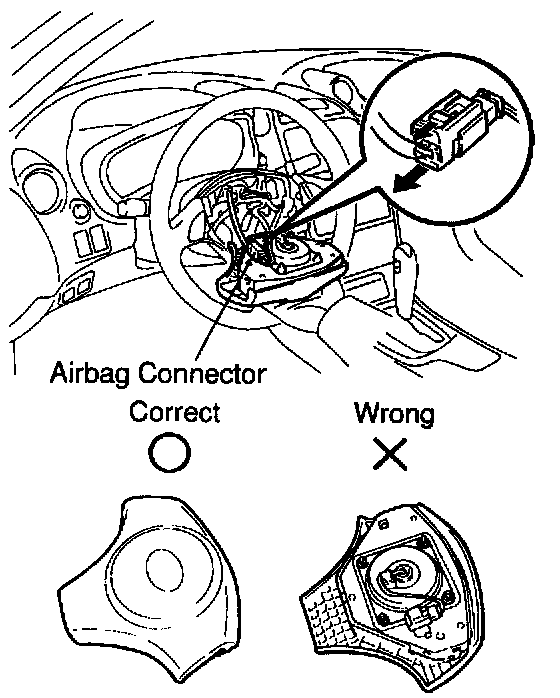
c. Pull out the wheel pad from the steering wheel and disconnect the airbag connector.
CAUTION:
^ When storing the wheel pad, keep the upper surface of the pad facing upward.
^ Never disassemble the wheel pad.
NOTICE: When removing the wheel pad, take care not to pull the airbag wire harness.
2. REMOVE STEERING WHEEL
a. Disconnect the connector.
b. Remove the steering wheel set nut.

c. Place matchmarks on the steering wheel and main shaft assembly.
d. Using SST, remove the steering wheel.
SST 09950-50013 (09951-05010, 09952-05010, 09953-05020, 09954-05021)
3. REMOVE LOWER NO.1 INSTRUMENT FINISH PANEL
a. Remove the 2 screws and disconnect the hood lock release lever.
b. Remove the 2 bolts and lower No.1 instrument finish panel.
c. Disconnect the connector.
4. REMOVE INSTRUMENT FINISH PANEL
Remove the 2 bolts and instrument finish panel.
5. REMOVE INSTRUMENT CLUSTER FINISH PANEL
Remove the 2 screws and instrument cluster finish panel.
6. REMOVE COLUMN UPPER AND LOWER COVERS
Remove the 3 screws, column upper and lower covers.

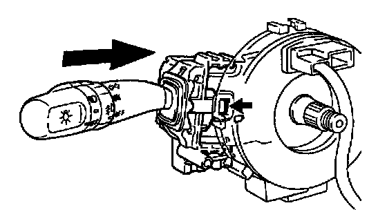
7. REMOVE SPIRAL CABLE, LIGHT CONTROL SWITCH AND HEADLIGHT DIMMER SWITCH AND WIPER AND WASHER SWITCH
a. Disconnect the 3 connectors from the spiral cable, light control switch and headlight dimmer switch and wiper and washer switch.
b. Disconnect the airbag connector from the spiral cable.
c. Push the claw and pull out the light control switch and headlight dimmer switch.
d. Employ the same manner described above to the wiper and washer switch.
e. Remove the spiral cable.
NOTICE: Do not disassemble the spiral cable or apply oil to it.

8. A/T: REMOVE KEY INTERLOCK CABLE
With the key in ACC, push the claw and pull out the key interlock cable.
9. REMOVE COLUMN HOLE COVER SILENCER SHEET
10. DISCONNECT NO. 2 INTERMEDIATE ASSEMBLY
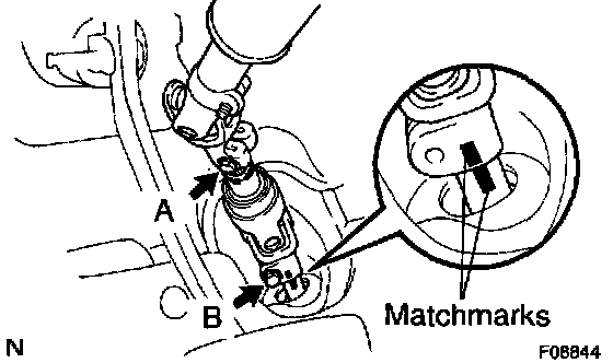
a. Place matchmarks on the No. 2 intermediate shaft assembly and intermediate extension.
b. Loosen the bolt A and remove the bolt B, then disconnect the No. 2 intermediate shaft assembly.
11. REMOVE STEERING COLUMN ASSEMBLY
a. Disconnect the connectors.
b. Remove the 2 bolts, nuts and steering column assembly.

12. REMOVE NO. 2 INTERMEDIATE SHAFT ASSEMBLY
a. Place matchmarks on the No. 2 intermediate shaft assembly and main shaft assembly.
b. Remove the bolt and No. 2 intermediate shaft assembly.
13. w/ Transmission shift switch: REMOVE TRANSMISSION SHIFT SWITCH ASSEMBLY FROM STEERING WHEEL
a. Remove the 2 screws.
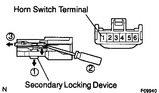
b. Disengage the secondary locking device of the connector.
c. Release the locking lug of the terminal 1 (horn switch terminal), and pull the terminal out of the rear.
d. Remove the transmission shift switch assembly.
14. w/ Speed control main switch: REMOVE SPEED CONTROL MAIN SWITCH ASSEMBLY FROM STEERING WHEEL
a. Remove the 2 screws.
b. Disengage the secondary locking device of the connector.
c. Release the locking lug of the terminal 1 (horn switch terminal), and pull the terminal out of the rear.
d. Remove the speed control main switch assembly.
15. w/ Transmission shift switch and speed control main switch: REMOVE TRANSMISSION SHIFT SWITCH ASSEMBLY AND SPEED CONTROL MAIN SWITCH ASSEMBLY FROM STEERING WHEEL
a. Remove the 2 screws from the transmission shift switch assembly.
b. Remove the 2 screws from the speed control main switch assembly.
c. Disengage the secondary locking device of the connector.
d. Release the locking lug of the terminal 1 (horn switch terminal), and pull the terminal out of the rear.
e. Remove the transmission shift switch assembly and speed control main switch assembly.
INSTALLATION
1. w/Transmission shift switch: INSTALL TRANSMISSION SHIFT SWITCH ASSEMBLY TO STEERING WHEEL
a. Install the transmission shift switch assembly.
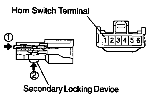
b. Push the terminal 1 (horn switch terminal) into the connector.
c. Engage the secondary locking device of the connector.
d. Install the 2 screws.
2. w/ Speed control main switch: INSTALL SPEED CONTROL MAIN SWITCH ASSEMBLY TO STEERING WHEEL
a. Install the speed control main switch assembly.
b. Push the terminal 1 (horn switch terminal) into the connector.
c. Engage the secondary locking device of the connector.
d. Install the 2 screws.
3. w/ Transmission shift switch and speed control main switch: INSTALL TRANSMISSION SHIFT SWITCH ASSEMBLY AND SPEED CONTROL MAIN SWITCH ASSEMBLY TO STEERING WHEEL
a. Install the transmission shift switch assembly and speed control main switch assembly.
b. Push the terminal 1 (horn switch terminal) into the connector.
c. Engage the secondary locking device of the connector.
d. Install the 2 screws to the transmission shift switch assembly.
e. Install the 2 screws to the speed control main switch assembly.
4. INSTALL NO. 2 INTERMEDIATE SHAFT ASSEMBLY
a. Align the matchmarks on the No. 2 intermediate shaft assembly and main shaft assembly.
b. Install the No. 2 intermediate shaft assembly with the bolt.
Torque: 35 Nm (360 kgf-cm, 26 ft. lbs.)
5. INSTALL STEERING COLUMN ASSEMBLY
a. Install the steering column assembly with the 2 bolts and nuts.
Torque: 21 Nm (210 kgf-cm, 15 ft. lbs.)
b. Connect the connectors.
6. CONNECT NO. 2 INTERMEDIATE SHAFT ASSEMBLY
a. Align the matchmarks on the No. 2 intermediate shaft assembly and intermediate extension.
b. Install the bolt B.
Torque: 35 Nm (360 kgf-cm, 26 ft. lbs.)
c. Torque the bolt A.
Torque: 35 Nm (360 kgf-cm, 26 ft. lbs.)
7. INSTALL COLUMN HOLE COVER SILENCER SHEET

8. A/T: INSTALL KEY INTERLOCK CABLE
With the key in ACC, push into the key interlock cable and install it.
9. INSTALL LIGHT CONTROL SWITCH AND HEADLIGHT DIMMER SWITCH, WIPER AND WASHER SWITCH AND SPIRAL CABLE
a. Install the spiral cable.
b. Push into the light control switch and headlight dimmer switch until the claw is latched.
c. Employ the same manner described above to the wiper and washer switch.
d. Connect the airbag connector to the spiral cable.
e. Connect the 3 connectors to the spiral cable, light control switch and headlight dimmer switch and wiper and washer switch.
10. INSTALL COLUMN UPPER AND LOWER COVERS
Install the column upper and lower covers with the 3 screws.
11. INSTALL INSTRUMENT CLUSTER FINISH PANEL
Install the instrument cluster finish panel with the 2 screws.
12. INSTALL INSTRUMENT FINISH PANEL
Install the instrument finish panel with the 2 bolts.
13. INSTALL LOWER NO. 1 INSTRUMENT FINISH PANEL
a. Connect the connector .
b. Install the lower No. 1 instrument finish panel with the 2 bolts.
c. Connect the hood lock release lever and install the 2 screws.

14. CENTER SPIRAL CABLE
a. Check that the front wheels are facing straight ahead.
b. Turn the cable counterclockwise by hand until it becomes harder to turn.
c. Then rotate the cable clockwise about 2.5 turns to align the marks.
HINT: The cable will rotate about 2.5 turns to either left or right of the center.
15. INSTALL STEERING WHEEL
a. Align the matchmarks on the steering wheel and main shaft assembly.
b. Install the steering wheel set nut.
Torque: 50 Nm (510 kgf-cm, 37 ft. lbs.)
c. Connect the connector.

16. INSTALL STEERING WHEEL PAD
NOTICE:
^ Never use airbag parts from another vehicle. When replacing parts, replace with new ones.
^ Make sure the wheel pad is installed with the specified torque.
^ If the wheel pad has been dropped, or there are cracks, dents or other defects in the case or connector, replace the wheel pad with a new one.
^ When installing the wheel pad, take care that the wirings do not interfere with other parts and that they are not pinched between other parts.
a. Connect the airbag connector.
b. Install the steering wheel pad after confirming that the circumference groove of the torx screws is caught on the screw case.
c. Using a torx socket wrench, torque the 2 screws.
Torque: 8.8 Nm (90 kgf-cm, 78 inch lbs.)
17. CHECK STEERING WHEEL CENTER POINT