Output Shaft

DISASSEMBLY

1. INSPECT 1ST AND 2ND GEARS THRUST CLEARANCE
Using a feeler gauge, measure the thrust clearance.
Standard clearance:
1st gear: 0.10 - 0.40 mm (0.0039 - 0.0157 inch)
2nd gear: 0.10 - 0.55 mm (0.0039 - 0.0217 inch)
Maximum clearance:
1st gear: 0.40 mm (0.0157 inch)
2nd gear: 0.55 mm (0.0217 inch)

2. INSPECT 1ST AND 2ND GEARS RADIAL CLEARANCE
Using a dial indicator, measure the radial clearance between the gear and shaft.
Standard clearance:
KOYO made: 0.015 - 0.058 mm (0.0006 - 0.0023 inch)
NSK made: 0.015 - 0.056 mm (0.0006 - o.od22 inch)
Maximum clearance:
KOYO made: 0.058 mm (0.0023 inch)
NSK made: 0.056 mm (0.0022 inch)
If the clearance exceeds the maximum, replace the gear, needle roller bearing or shaft.

3. REMOVE REAR RADIAL BALL BEARING, 4TH DRIVEN GEAR AND OUTPUT GEAR SPACER FROM OUTPUT SHAFT
a. Using SST and a press, remove the rear radial ball bearing and 4th driven gear.
SST 09950-00020
HINT: Support the output shaft assembly by hand so that it will not be dropped off.
b. Remove the output gear spacer.
4. REMOVE 3RD DRIVEN GEAR, 2ND GEAR, NEEDLE ROLLER BEARING, SPACER AND NO. 2 SYNCHRONIZER RING

a. Shift the reverse gear into the 1st gear.

b. Using SST and a press, remove the 3rd driven gear and 2nd gear.
SST 09950-00020
HINT: Support the output shaft assembly by hand so that it will not be dropped off.
c. Remove the needle roller bearing, spacer and No. 2 synchronizer rings.
5. REMOVE SNAP RING
Using 2 screwdrivers and a hammer, tap out the snap ring.
HINT: Take care not to damage the journal surface of the output shaft.

6. REMOVE REVERSE GEAR ASSEMBLY, 1ST GEAR, NO. 1 SYNCHRONIZER RING, NEEDLE ROLLER BEARING, 1ST GEAR THRUST WASHER AND BALL
a. Using a press, remove the reverse gear assembly, 1st gear and No. 1 synchronizer ring.
HINT: Support the output shaft assembly by hand so that it will not be dropped off.
b. Remove the needle roller bearing and 1st gear thrust washer.
c. Using a magnetic finger, remove the ball.
7. REMOVE SNAP RING
Using 2 screwdrivers and a hammer, tap out the snap ring.
HINT: Take care not to damage the journal surface of the output shaft.

8. REMOVE FRONT BEARING INNER RACE
Using SST and a press, remove the front bearing inner race.
SST 09950-00020
NOTICE: When replacing the front bearing ironer race, replace the output shaft front bearing along with it.
HINT: Support the output shaft by hand so that it will not be dropped off.

9. DISASSEMBLE REVERSE GEAR ASSEMBLY
a. Remove the reverse gear from the No. 1 clutch hub.
b. Remove the 3 No. 1 shifting keys and No. 1 shifting key springs from the No. 1 clutch hub.
INSPECTION

1. INSPECT 1ST GEAR SYNCHRONIZER RING
a. Check for wear or damage.
b. Check the braking effect of the synchronizer ring. Turn the synchronizer ring in one direction while pushing it to the gear cone. Check that the ring locks.
If the braking effect is insufficient, apply a small amount of the fine lapping compound between the synchronizer ring and gear cone. Lightly rub the synchronizer ring and gear cone together.
NOTICE: Ensure the fine lapping compound is completely washed off after rubbing.
c. Check again the braking effect of the synchronizer ring.

d. Using a feeler gauge, measure the clearance between the synchronizer ring back and gear spline end.
Minimum clearance: 0.75 mm (0.0295 inch)
If the clearance is less than the minimum, replace the synchronizer ring, and apply a small amount of the fine lapping compound on gear cone.
NOTICE: Ensure the fine lapping compound is completely washed off after rubbing.

2. INSPECT 2ND GEAR SYNCHRONIZER RING
a. Check for wear or damage.
b. Check the braking effect of the synchronizer ring.
Turn the synchronizer ring in one direction while pushing it to the gear cone. Check that the ring locks.
If the braking effect is insufficient, replace the synchronizer ring.

c. Using a feeler gauge, measure the clearance between the synchronizer ring back and gear spline end.
Minimum clearance: 0.70 mm (0.0276 inch)
If the clearance is less than the minimum, replace the synchronizer ring.

3. INSPECT GEAR SHIFT FORK AND REVERSE GEAR CLEARANCE
Using a feeler gauge, measure the clearance between the reverse gear and gear shift fork.
Maximum clearance: 0.35 mm (0.014 inch)
If the clearance exceeds the maximum, replace the gear shift fork or hub sleeve.

4. INSPECT OUTPUT SHAFT
a. Check the output shaft for wear or damage.
b. Using a micrometer, measure the outer diameter of the output shaft journal surface.
Minimum outer diameter:
Part A: 32.985 mm (1.2986 inch)
Part B: 37.985 mm (1.4955 inch)
Part C: 31.985 mm (1.2592 inch)
If the outer diameter is less than the minimum, replace the output shaft.

c. Using a dial indicator, check the shaft runout.
Maximum runout: 0.03 mm (0.0012 inch)
If the runout exceeds the maximum, replace the output shaft.
REASSEMBLY
HINT: Coat all of the sliding and rotating surfaces with gear oil before reassembly.

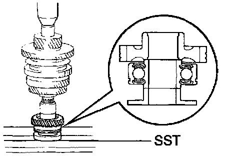
1. INSTALL FRONT BEARING INNER RACE
Using SST and a press, install the front bearing inner race.
SST 09223-50010
NOTICE: Be sure to install the front bearing inner race in the correct direction, as shown in the illustration.

2. INSTALL SNAP RING

a. Select a snap ring from the table that will make the thrust clearance of the front bearing inner race less than 0.1 mm (0.0039 inch).
b. Using a screwdriver and hammer, tap in the snap ring.
HINT: Take care not to damage the journal surface of the output shaft.
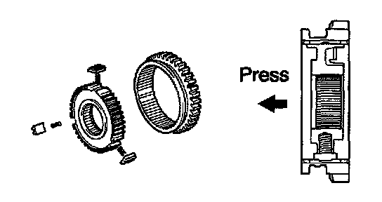
3. ASSEMBLE REVERSE GEAR ASSEMBLY
a. Install the 3 No. 1 shifting key springs and No. 1 shifting keys to the No. 1 clutch hub.
Install the No. 1 clutch hub to the reverse gear.
NOTICE: Assemble the No. 1 clutch hub and reverse gear in the direction shown in the illustration.

4. INSTALL BALL, 1ST GEAR THRUST WASHER, NEEDLE ROLLER BEARING, 1ST GEAR, NO. 1 SYNCHRONIZER RING AND REVERSE GEAR ASSEMBLY TO OUTPUT SHAFT
a. Using a magnetic finger, install the ball to the output shaft.
b. Fit the 1st gear thrust washer groove securely over the locking ball when installing the thrust on the output shaft.

c. Apply gear oil to the needle roller bearing and install it.
d. Install the 1st gear and No. 1 synchronizer ring.
NOTICE: Distinguish the No. 1 synchronizer ring by the teeth on the synchronizer ring.

e. Place the reverse gear assembly and align the No. 1 synchronizer ring slots with the No. 1 shifting keys.

f. Using a press, install the reverse gear assembly.
NOTICE:
^ Be sure to install the reverse gear assembly in the correct direction, as shown in the illustration.
^ When installing, make sure the ball is placed in a groove of the 1st gear thrust washer.

5. INSTALL SNAP RING

a. Select a snap ring from the table that will make the thrust clearance of the No. 1 clutch hub less than 0.1 mm (0 0039 inch).
b. Using a screwdriver and hammer, tap in the snap ring.
HINT: Take care not to damage the journal surface of the output shaft.
6. INSPECT 1ST GEAR THRUST CLEARANCE

7. INSTALL SPACER, NEEDLE ROLLER BEARING, NO. 2 SYNCHRONIZER RING, 2ND GEAR AND 3RD DRIVEN GEAR
a. Install the spacer
b. Apply gear oil to the needle roller bearing and install it.
c. Place the No. 2 synchronizer rings on the 2nd gear.
NOTICE:
^ Properly fit the synchronizer middle ring claws into the holes in the 2nd gear.
^ Distinguish the No. 2 synchronizer ring by the teeth on the synchronizer ring.

d. Place the 2nd gear with the No. 2 synchronizer rings and align the No. 2 synchronizer ring slots with the No 1 shifting keys.
NOTICE: Fit the synchronizer inner ring claws into the slots in the No. 1 clutch hub.

e. Using a press, install the 3rd driven gear.
NOTICE: Be sure to install the 3rd driven gear in the correct direction, as shown in the illustration.
8. INSPECT 2ND GEAR THRUST CLEARANCE
9. INSTALL OUTPUT GEAR SPACER, 4TH DRIVEN GEAR AND REAR RADIAL BALL BEARING
a. Install the output gear spacer.
b. Using SST and a press, install the 4th driven gear and rear radial ball bearing.
SST 09608-00071
NOTICE: Be sure to install the 4th driven gear and rear radial ball bearing in the correct direction, as shown in the illustration.
HINT: Set SST to the bearing inner race securely.